Search Build Log

Showing posts with label 17 - Leading Edges. Show all posts

5 Jun 2021

17-09: Landing Light Lenses

In order to fit the fuel tanks vertically on the wing cradle, i could only have one wing in the cradle at a time, as i needed access to both sides of the wing.

So while the other wing was one the bench, it was an ideal time to install the landing light lenses. 

To start, i masked the wing to protect the inside of the lens, then placed it over the cut-out in the wing on the outside and traced a line 3/4" from the cut-out. 

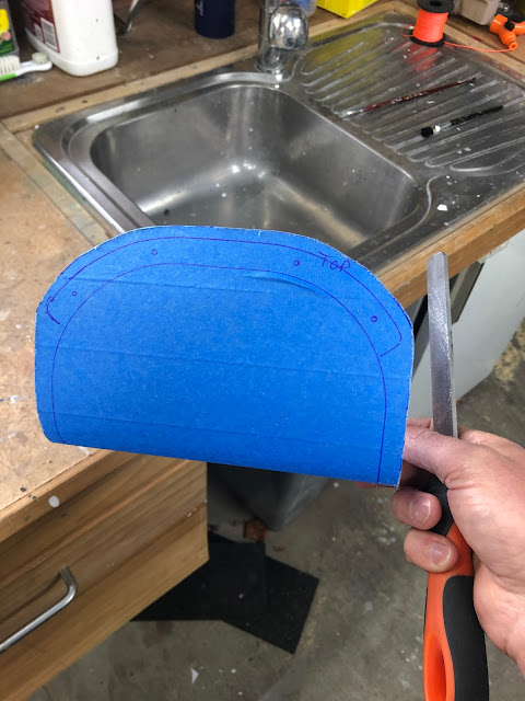
I then covered the outside of the lens with masking tape, and holding the lens up to the light traced the 3/4" line onto the masking tape. 


To cut the lens i used my Dremel with a plastic cut off disk. This cuts through the lens very easily - it sort of melts the lens. The only thing to be careful of is it splatters little pieces of melted plastic everywhere, as well as tiny 'spider webs' of plastic. There were webs floating around everywhere. Lucky i was wearing a full face shield - probably should have been wearing a respirator.


Little pieces of plastic stuck to my face mask.

I cleaned up these cuts with a file, then placed the lens back into the cut-out. The instructions state:

I found that if you placed the lens right up to the rib flange, there would not be enough space on the lens to mark a 1/4" gap. But i was able to place the lens over the top of the rib flanges, but push it right up against the edge of the dimples in the rib flanges - this gave enough edge distance. 
This shows how the edge distance is not enough to fit the 1/4" margin, unless the lens was moved right up to the edge of the rib flange dimples.


I also found the method in the plans to pull the lens forward was not very good at getting the lens tight to the skin. A better method was to 'back tape' the pieces of tape attached to the lens, and pull the tape back, taping it onto the skin at the top and bottom. 


I was then able to mark the lens cut-out on the tape as well as the screw holes. I removed the lens and marked the positions of the backing plates, then marked a cut line which was 1/4" at the top and bottom of the lens, and 3/8" on the sides. The plans called for 1/4" on the sides as well, but 3/8" seemed better. 


This was then cut out to the new line and the edges files smooth and given a bevelled/rounded edge. I made sure to file off all the large cut marks. I then sanded with 240 grit so the edges were smooth. 

The lens was then put back into the wing and pushed tightly up to the front as far as it would go. I used the double backed tape again to hold it tight. I was then able to match drill the lens using a #30 Plexi-drill bit, clecoing each hole as i went. These bits worked great - i practiced on the scrap offcuts to make sure i didn't stuff up the part.


These holes were updrilled to #27, the backs were deburred and then i countersunk the front for a #27 (#6 screw) dimple. 

The matching holes on the wing skin were also updrilled to #27, then dimpled. 

The backing plates were stuck onto the inside of the lenses using double-sided tape, the masking tape was removed from the lenses and i was able to install the lenses into the wings with no real issues. I can see why you need to stick the backing plates to the lens - with a landing light installed it would be impossible to hold them in place while screwing the lens in place.


This is just my shop torch!


The lenses were then removed, placed back in the protective plastic bags they came in, and reinstalled for storage on the wing cradles until the wings are needed later on. 

And that completed the leading edges! 

Leading Edge Stats

The leading edges were started on the 27 July 2020 and finished on 15 Jun 2021 - 323 Days  (10 Months / 19 Days). 

Total rivets set in the leading edges: 1086.


27 May 2021

17-08: Riveting Leading Edges to Wing

Wing Cradle Modification

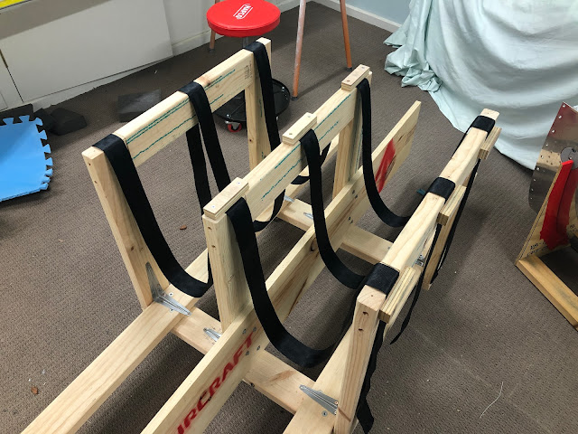
In order to hold the wing in the wing cradle once the leading edges were installed, i had to modify the cradle with a sling arrangement such that the wing would be safely held with the leading edges in place. 

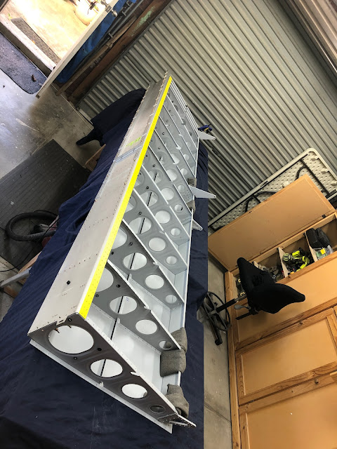
The wings were removed from the cradle - one put on saw horses temporarily, and the other placed on the bench. The one on the bench was placed so i could cleco on the leading edge for riveting. I used shot bags to make sure it didn't fall off the bench, but most of the weight is aft of the spar anyway.


The wooden "cross bars" that were at the outboard end of the cradle were removed, and i installed some metal shelf brackets to help brace the vertical 'legs' of the cradle, and stop them leaning inward with the weight of the wing. This was probably overkill, but i had the brackets in the cupboard so i figured it wouldn't hurt.


I used some solid 3/4" plywood to make 9 'clamps'. 


I purchased some 'seat belt' type strapping which was good for 2,200 kgs - should just be enough :) 


I measured the leading edges, and cut & clamped the strap so that once the wing was placed in the cradle with the leading edges installed, the spar would be relatively level, and i would have access to set the leading edge skin to spar rivets.


Riveting on the Leading Edges

The first leading edge was clecod on, and the the fit against the top skin was checked. I made sure there was about a 1/32"-ish gap the whole way along the leading edge skin - basically so i could just see a sliver of green primer on the spar flanges through the gap. These will be filled with paint eventually, i think. I also made sure that the tie down rings screwed in without interfering with the skins.
I had to lay on the ground with a torch, to check the fit of the leading edge skin against the top wing skin.

All ribs except the most onboard one was installed with pull-rivets (of a couple of different lengths). I made sure to use a piece of cardboard on the skins in case the rivet puller bumped into the skin when the tail snapped off (as happened on the rudder skins). I used a small piece of rudder trailing edge as a wedge to allow the rivet puller to fit (where this was necessary). 

Here you can see the little wedge in action

This makes me happy


The inboard most rib was installed with AN470 rivets - i used the offset rivet set on these at quite a high pressure of 60 psi. 


Bucking bar bruises

Once the ribs were riveted to the spar, the wing was placed in the cradle. I was able to use the squeezer to set all the flush rivets along the bottom flange of the spar, but was not able to reach the top skin rivets by myself. My mate Kingers helped me on this one - i ran the gun and he was on the bar. We used a couple pieces of thin ply as a shim to make sure the bar stayed normal to the spar flange and all these rivets went without having to drill one out.
The setup on the cradle was perfect - very easy access to the top skin rivets. For the second wing, we just swapped the wings over and put one wing back on the workbench. It will stay there anyway, in preparation to install the fuel tanks.


Access using the squeezer to the bottom flange of the spar was easy using this arrangement. I am very happy with this cradle - it has worked out great.


Right Wing - CLECO Free since 2021!

Next up is the landing light lenses, priming the outside of the fuel tanks and then installing them on the wing.


14 Sept 2020

COVID: Working out of order

 A short post to explain why it seems like i'm working on multiple sections at once! 

Due to COVID, i have been unable to rivet the top wing skins to the spar / rib assembly. I know a few builders have done this solo, but i would prefer to back rivet these using a long back-rivet set i have borrowed from a mate of a mate; so for now the top wing skins completely ready for installation, but are in storage for now. 

Since they were on hold, i decided to keep moving by beginning work on the leading edges. Again, i got to a bottleneck with this section. I completed the riveting of the leading edges however, since the top wing skins are installed with the spar shimmed to level on the work bench, I could not complete the chapter by riveting the leading edges to the spar. 

So, moving on to the fuel tanks! 


9 Sept 2020

17-06: Leading Edge Riveting

It feels good to be back into riveting - like i'm actually making progress! All in all, the leading edges went together very quickly - with only 9.5 hours of work for both sides. One leading edge was done at a time due to not having enough clecos to put the ribs into both sides at once.

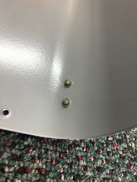
Work started with back riveting the left hand side access panel doubler to the skin. At the same time, i filled the 2 pre-punched holes where the stall warning vane is supposed to exit, with rivets.


Once this was done the skin was placed into the cradle and the ribs were carefully clecod in place - a cleco was used in every hole. As per the instructions, the aft most rivet in each rib was done first. I then worked along one side of the skin from the root end to tip, then back again one rivet row lower, then switched to the other side (top to bottom) and did the same thing. The rivets on the root end (the splice rib / splice strip) were done using the squeezer and the rest were done with a swivel mushroom set in the gun and a small tungsten bucking bar. I ran a hose from the other end of the shed and kept that regulator at 90psi for the squeezer, and ran the gun on a separate hose at 28psi - so i didn't keep having to adjust things when i switched to the squeezer. I find this low PSI helps to keep the skins flat and prevent them being pushed in too much when you are bucking rivets between skins and ribs. A higher pressure results in a sort of large (1" diameter) depression around the rivet - like an underset dimple.


Foam floor tiles were cut and places inside in case of a dropped bucking bar


Even though the skin is curved here, you can see that around the rivet underneath the ruler there is almost no large depression - the skins stay quite flat. 

I was able to get to all the rivets in the cradles, except the last 1 on the bottom side, and the last 3 on the top side. For these last ones, the assembly was placed on my work bench using pieces of foam and a couple of clamps to keep it stable. I thought these front ones would be difficult, but i was able to reach in and set the bar up fine, and focused my attention on not letting the gun wander.


Once the ribs were done, the assembly was placed back into the cradle and the J stiffners were slid in place and riveted with the gun and bar. Finally the landing light bracket was also put in place and riveted the same way.

The black paint hardened to a good tough surface and i am very happy with how that came out - i was able to get it together with no scratches. I won't paint over the shop heads of the rivets - i think it looks good the way it is.


I was actually still fairly proficient and surprisingly, only had to drill out 3 rivets in the 2 leading edges.
An expensive bookcase / stubby holder.
The last step was to install the access panel into position to check the fit. I elected to use AN507C632-R6 screws instead of the R8 length as these were just too long. (at least 1/4" sticking out the back of the nutplates).

The -R6 screws were a much better length than the R8.


And of course, every good artist signs their work when they are done: