I finally received my missing Flap Torque tube from Van's - it was missing when i cut the UHMW blocks and test fit the flap torque tubes, back in Chapter 32. So i gave the newly arrived torque tube the same treatment - sanding down the edges of the powder coat transition, as well as a general sand all over the surface. I added some grease and did a test fit to the airframe - and the new torque arm slid in fine.
Flap Crank Twist
So, onto page 34-02 for the drilling of the torque tubes to the flap crank. Page 34-02 asks you to clamp the flap crank to the table in order to complete the subsequent steps. To do this, i rolled back the carpet on my workbench and immediately noticed a problem - there was a slight twist in the flap crank. The holes for mounting the flap actuator, were not planar with the flap torque tubes.
 |
| Here you can see, with the tube end parallel to the bench, the flap actuator end is not planar. |
 |
| This is the opposite way - with pressure down on the front of the flap crank, the flap actuator end is parallel to the bench, but he flap tube end is not. |
 |
| It is off by a country mile. Expected i guess with a welded part. |
 |
| This shows with the flap torque tube installed and parallel with the bench, the flap actuator end of the weldment is not parallel, and was floating above the table. |
The issue with this, is the only place i can clamp that weldment to my table is at the front. But by applying pressure it throws the torque tube end out of alignment - since the outer end of that tube needs to be flat and clamped to the bench (with the alignment template), i needed to add a shim under the forward end of one side of the flap crank. This allowed me to clamp it to the table, while keeping the torque tube end parallel to the bench. The misalignment at the flap actuator end will not be an issue, as the flap actuator has a CM4-4 rod end bearing to interface with the flap crank.
 |
| A scrap was used as a shim. |
 |
| With the shim in place, the flap torque tubes are parallel to the bench. |
Drilling the Torque Tubes
So with that sorted, I was able to clamp the flap crank to the table, slide on the aileron alignment jig (which turns out to be a multipurpose tool!), and set the required length of the tubes. I was then able to clamp down the outboard end of the rube, and match drill #30 the first hole. The plans ask you to match drill the upper, outboard hole in the flap crank, then match drill the hole opposite this, before removing the clamp. This was impossible, as the opposing hole was facing the work bench. So I just match drilled the other (inboard) hole on the top of the flap crank, before removing the clamp, flipping it over and match drilling the other holes #30. They were then drilled to #19, and reamed to 3/16" for an AN3 bolt. Everything was then removed and deburred.
 |
| The multi-purpose aileron alignment jig! |
 |
| Since my brain is made of metric cells, i marked the required distance (23 5/16") onto my tape. |
 |
| I used my screw on toggle clamp to hold the tube down for match drilling. |
Priming the inside of the tubes
I primed the inside of the tubes using Norglass ShipShape, 2 part epoxy paint. I first dragged a rag soaked in Iso back and forth, then a scotchbrite pad, then another rag. One end of the tube was covered in masking tape (blocking it off). I poured in the paint and capped the open end with tape. Then sloshed the paint around and left the tube hanging on the edge of a drawer, draining the excess paint into a cup.
Installation into the Fuselage
Finally, the torque tubes were generously slathered in grease and slid right in with no troubles. I was then able to install the called out hardware and torque the nuts.
 |
| The insides of the tubes are nicely coated in paint. |
 |
| I checked the rudder cable were above the flap torque arms on each side using a mirror. |
 |
| This is why all my tools are on wheels - was not able to slide the right tube in place, as my power-tool bench was in the way. Luckily, i just moved it out of the way. |
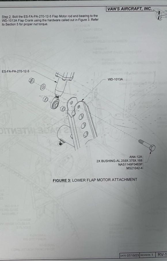
Pinning and checking the flap motor
EDIT: The dimensions for the flap motor shown in the Van's plans, are not correct if you modify the motor mounts in accordance with the PH Aviation Instructions. They are only correct if you use the new Van's flap motor mount brackets. The correct dimensions are outlined here.
The flap motor i am using is not stock, but is a unit i purchased from Van's which was offered as a replacement for the RV10 (
as detailed here). Because of this, there is a bit of a lack of information on how to retrofit the unit into a RV-14. There are the PH Aviation Instructions (which i used to modify the flap brackets), and there are the RV10 Alternate Flap motor instructions. Unfortunately, the RV14 flap motor retrofit instructions (OP-65) have not been published as yet. However,
on the forums people were reporting that their fuselage kits were arriving with the alternate flap motor, and the printed instructions showed how to install it! So luckily, i was able to glean some information from the forums to install the rod end bearing, and set it's length. I was also able to check the throw of the motor was correct (which it was). Once this was done, i wired on a CPC Series 1 connector, and test fit the motor into the aircraft using an AN5 and AN4 bolt - the actual hardware (correct length bolts) is on it's way.
 |
| The printed RV14 Instructions shipping with the current fuselage kits has instructions for installing the CM4-4 rod end bearing, and the correct length for the unit. |
 |
| This hardware should be perfect. |
 |
| This hardware is not correct due to the custom made flap bracket modifications i made. I need a longer bolt, and no bushings. |
 |
| The wiring colour matched the actual motor. There was also a black wire which was snipped off. |
 |
| The throw of the motor is spot on. |
 |
| A free-hanging male (pins) CPC connector was installed on the motor (the tape is some female sockets pushed on for testing). |
 |
| My wiring diagram was kept up to date and connector and wire gauge information updated. |
Of course, i had to check that the thing worked:

.png)
.png)