Search Build Log

Showing posts with label 15 - Rear Wing Spar. Show all posts

6 Jul 2020

15-02 -> 04: Rear Spar Riveting

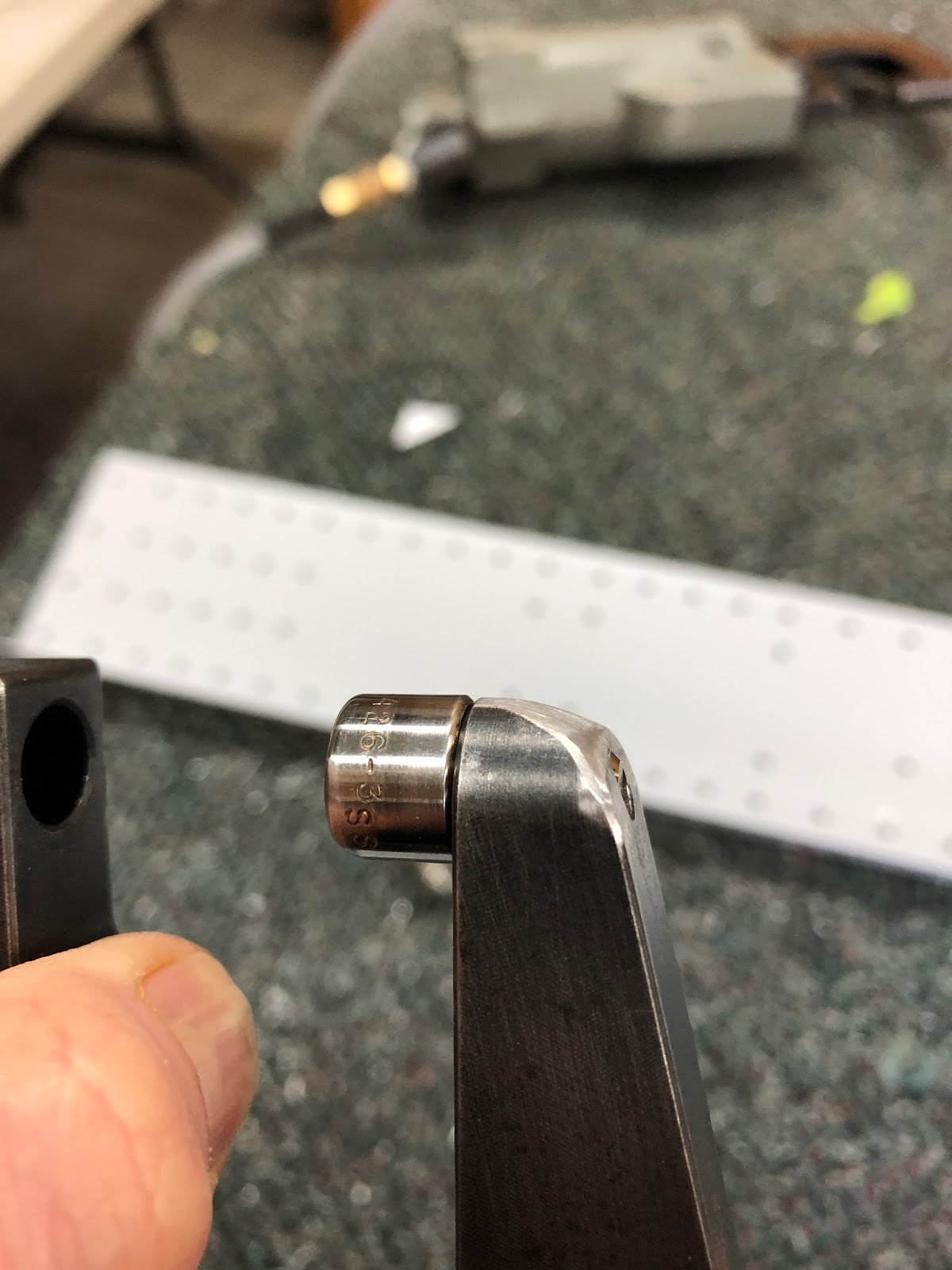
Aileron Hinge Brackets


Page 15-02 has you riveting the inboard and outboard hinge brackets together. SB 16-03-28 dated Mar 11, 2018 was used to construct both inboard aileron brackets. I was able to use the pneumatic squeezer to set all rivets except the long -11 rivets which go through both angles at the bottom of the inboard aileron bracket - the pneumatic squeezer didn't have enough 'throat' to reach. So the hand squeezer was used for these.
These are the outer aileron brackets (end of the wing spars)


The hand squeezer was used on these giants!

These are the inner aileron brackets made as per the SB plans. 


Rear Spar Riveting

The rear spar prep started with the dimpling of the skin holes on the spar flanges. I was able to fit my pneumatic squeezer in here with no real issues; although, for the lower flanges which are bent more than 90deg i had to grind the top of the squeezer yoke down so that it would fit. Just a lot of holes! 
Careful grinding on the belt sander to get the toke to fit.


Once this was done, i carefully clecod all the components of the spar in place and taped off any holes which did not get riveted at this time. This includes a horizontal row of holes for the aileron and flap gap covers, as well as any place where there was a rib. I riveted the doublers on first, then did the inboard aileron brackets once the doublers were on. 


All rivets on the rear spar were set using the pneumatic squeezer. Once i set it up for a particular rivet length, i set all rivets on both spars that were this length, starting with the shortest and moving to the longest. There were a few rivets on the aileron brackets i could not get the squeezer onto straight - so i tried using the gun and bar. These rivets were ok, but not as consistent as the others - so i bit the bullet and ground down the longeron yoke so that it would fit. 

For all rivets set at this stage, i put the manufactured head on the aft of the spar - the parts were basically the same thickness and this worked out very well. No puckering was observed anywhere. 
The forward side of the left aileron bracket.

The aft side of the left inboard aileron bracket

The forward side of the right aileron bracket

I tried using the gun and bar on these rivets, but didn't like the lack of consistency. I think the spar was moving around a little. 

Did't have too many tipped over rivets! 

The longeron yoke was ground down to fit around the rivets on the aileron brackets and resulted in much more consistent rivet set.
 

Rear spar riveting complete
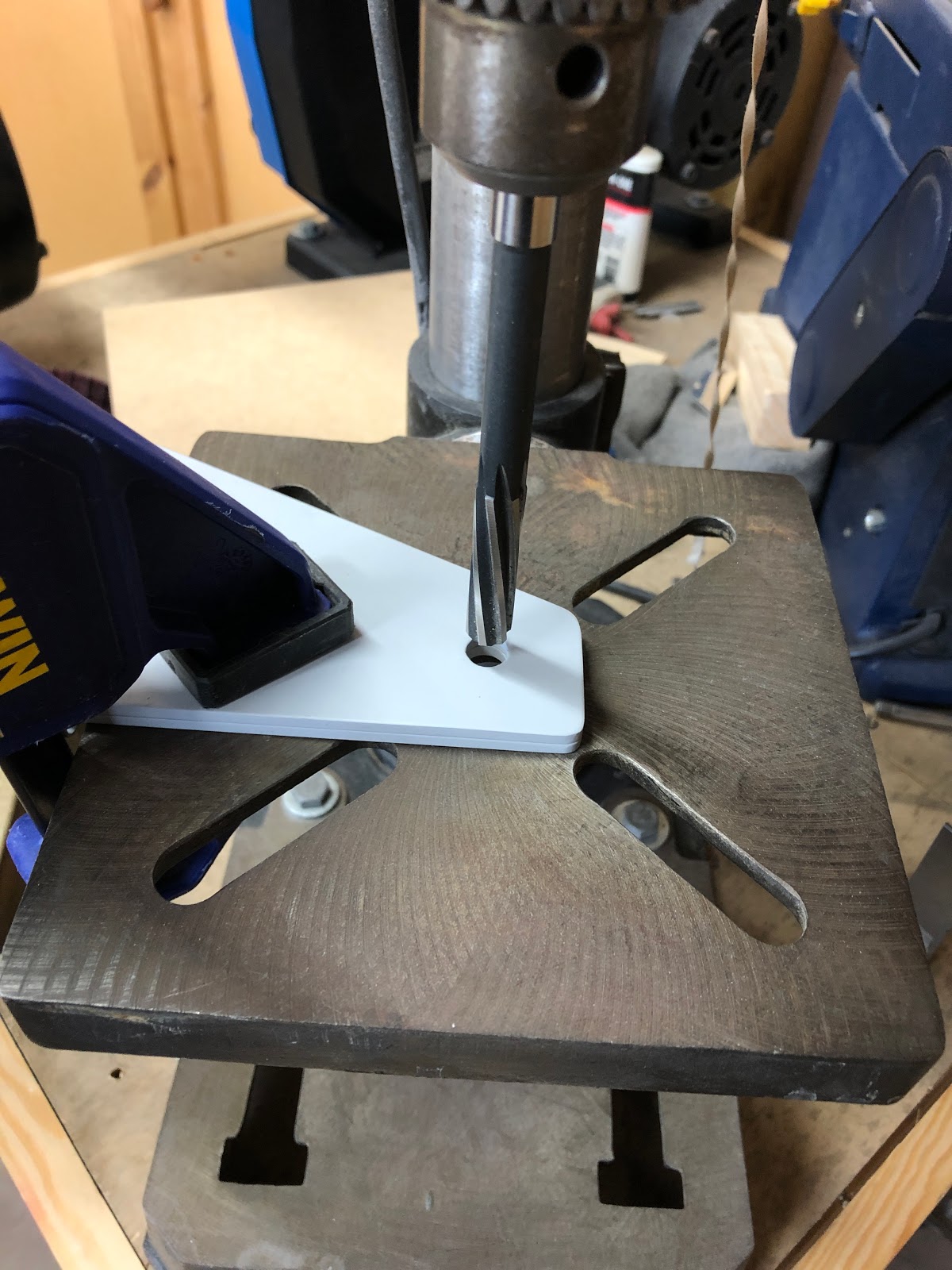
A "Critical Hole"

The bolt holes at the end of the rear spar where the wing bolts onto the fuselage are 11/32" and must be reamed to 3/8" (for AN6 bolts later). For this i set the rear spar up as level as i could, and triple checked that the reamer was 90deg in both planes to the table of the drill press. I then clamped the parts down, set the drill press to the slowest speed (900 rpm) and tried to ream the fist hole. The reamer was chattering a lot, so i stopped the drill and hand turned the chuck to get the reamer started, then it went nicely through the hole. The hole was checked with a caliper was was indeed 3/8". I deburred the edges of the holes, then added a little primer into the holes with a cotton bud. 


Rear Spar Riveting

Next up was the actual riveting of the spars to the rear of the wing ribs. When clecoing the spar on, i noticed that i had forgotten to dimple the flanges of the small "flap hinge" ribs at each flap bracket location. Checking back on the plans, this was called out on page 14-02, Step 2 but i had missed it. Goes to show that trial fitting parts to see if they make sense is a good idea. I was able to dimple these in-situ with the hand squeezer. 
Lucky i noticed these!
I clecod the rear spars onto the wings one at a time. I placed the wing on the bench to make the riveting easier. Earlier i elected to put the manufactured head on the aft side of the spar (as the parts were the same thickness). However, for the wing ribs the flanges are much thinner than the spars and i didn't think it was a good idea to be placing the shop head on the thin flange. So for these rivets i placed the manufactured head on the rib flange - this allowed me to pull on the squeezer body to make sure the rib flange was flush to the spar. I think all these rivets turned out well. 

I was able to get to all the spar to rib rivets using the squeezer except the lower rib attach rivet on the rib adjacent to each of the inboard aileron attach brackets - for these the aileron bracket got in the way of the squeezer body. I used a gun and a bucking bar for these and they turned out fine.

Left wing spar clecod in place ready for riveting

The shop heads were placed on the rear of the spar.

The manufactured heads were placed on the rib flanges
The line of holes left open are where the flap gap fairing will be installed later.


I was able to use the squeezer to get to all rivets except the lower rivet on the rib which is next to the inboard aileron bracket.

Thankfully i only had to drill out one rivet - had to pull out the big bertha #40 drill bit to get this done!
The only exception to the rivet direction was the rib attach rivets at the inboard end of the wing where there are 2 doublers. I decided that if i placed the shop head aft, these may interfere later with the setting of the skin rivets in this area, so i squeezed them with the shop head on the rib flange, and used a piece of plastic tubing to hold the rib flanges down. There was only a tiny bit of lifting of the rib flange. 
The rivets on the far left and right of this doubler attach the ribs to the spar - i placed the manufactured head aft to ensure clearance when setting the skin rivets later.

Where there was just a single doubler and clearance was not an issue, the shop head was placed aft like the rest of the ribs.

Rear spars complete - starting to look like a pair of wings! 


Here's hoping i haven't just built 2 left wings! 

15-03: Outboard Aileron Bracket Doubler - rectification!

A plan of action

As detailed in this post i messed up the outboard aileron bracket doublers by match drilling them to the root end of the spar, not the tip end. Doh.

These parts can't be reused, so i will need new ones. They are only $2.30 each so no big deal - however, due to COVID-19 there are almost no flights to and from the US at the moment, so the shipping is likely to be in the order of $50 for these 2 little parts (FedEx and DHL are still flying), and a lead time of 5-6 weeks (some are saying 10 weeks!). So i really need another solution.

The parts in question are 2024-T3 aluminium and are 0.040" thick.


There happens to be a piece in the trim bundle which is the same thickness, and the correct width as well! But i am not sure what the temper of this piece is, and so if it is suitable or not.


Not knowing the temper, i emailed Van's to ask if the trim bundle piece would be suitable:

So it seems the trim bundle piece is good to go!

The parts have a 1/4" inside radius bend at the top to allow them to nest inside the spar flanges, so i will need to bend the trim bundle piece to this radius.

In order to make this bend, I ordered the tool below:

Replacing the part

So due to COVID-19, it turns out the tool above won't be here for a couple of weeks!!! Argh - it is coming from the other side of the country. However, i was able to have a go at a massive bending brake at the local maintenance shop at the airport where i work, and got the bends done anyway. I added some radius shims to the bender to get the 1/4" radius on the part. 


These new doublers were match drilled to the spars (at the correct end this time!) then the flanges and length were trimmed to fit the spar. Much quicker than waiting for a new part from the US. 

23 Jun 2020

15-02->04: Rear Spar Parts Prep

Outboard Aileron Bracket

15-02 starts with preparation of the parts of the outboard aileron brackets.

Inboard aileron brackets as per SB 16-03-28

The inboard aileron brackets were prepped according to SB 16-03-28 dated Mar 11, 2018 - this includes the countersunk holes on the inboard angle bracket (lower 3 holes). The earlier dated versions of this SB used AN470 rivets but there was some interference with the ailerons (apparently). Interestingly, the parts for the original inboard brackets were not supplied with the the kit - only the parts for the SB.

There are a lot of parts in the SB kit - at least in the instructions there are pictures of both the left and right brackets.
The aileron bracket parts after priming

Rear Spar Doublers

There are 3 x 0.040" thick doublers that nest inside the flanges on the aft face of each spar. One for the outboard flap bracket, and one for each aileron bracket (the inboard flap bracket doesn't have one - probably because of the number of ribs in this area). The plans call for the match drilling of these doublers to the spars - easy peasy lemon squeezy. Such a simple step.... 

Each one was clamped to the spar, then as i progressed with the match drilling i added clecos. The outboard aileron bracket doublers were aligned with the end of the spars and drilled. 


WOW - what a good job i have done here.
The inboard aileron and flap doublers had a line drawn on them 5/16" in from the ends, which was aligned with the centre of a row of holes before match drilling. 

The line drawn 5/16" in from the edge of the doubler is aligned with the holes.
See - easy right! But wait:
The doubler must be aligned to the end of the spar... 

To the OUTBOARD end of the spar - where the aileron bracket is!
OOPS: It turns out that i did not have my head on straight, and i inadvertently drilled the OUTBOARD aileron bracket doubler to the root end of the spar:
Such nice match drilling..

But it should have been match drilled to this end! 

A lesson learned

The lesson i took away from this is, if i am going to continue to work both the left and right sides of the aircraft at the same time, i really need to mark the orientation of parts AND to understand what the part is for and were it goes. If i had have marked the spar before drilling and understood that this doubler goes under the aileron bracket, i might have avoided this mistake. I have an idea to fix this - more on that later! 

Rear Spar Doublers (post headslap)

Continuing on the rear spar doublers, i needed to open up the hole in each side where the aileron pushrod will connect to the aileron. This was done with a step drill, dremel/cutting bit/sanding drum bit, and a file. 


This doubler is shocked that i destroyed the outboard doubler. 


This cutting biy worked very well for removing the bulk of the material..

..and a sanding drum bit finished it off. 
Der..

Rear Spar Attachment Doublers

After the above doublers were done, i deburred the thick wing spar attachment doublers and drilled the attach hole on the small one to 11/32" using the drill press. Then the whole assembly (minus the outboard aileron bracket doubler of course) was clecod to the wing. The assembly was final reamed to the wing ribs, then removed and the remaining holes were reamed on the bench (where there were no ribs involved). There were 6 holes on ribs 2 & 3 which were match drilled from the attachment form doublers to the ribs. Of note was that i had to increase the width of the spar flange cutouts where they went around the flap brackets by 1/16", because they were rubbing on the flap brackets.
I checked about 4 times that the attach doublers were not on upside down

Only the aileron attach angle brackets (front and back) were attached for final reaming.

the gap between the spar flanges was increased by about 1/16" to clear the flap brackets


These 6 holes were match drilled to the ribs.

Countersinking Rear Spar

The plans call for countersinking the flanges of the rear spar where the doublers are located for a skin dimple, so these were done 0.007" deeper than flush. I did this with the doublers in place (and will have to do this to the outboard doubler locations when i fix that little mistake). Similarly, the rear spar attach doublers were countersunk for the head of a rivet for the lower rivet line, and for a skin dimple (the flap gap cover) - again 0.007" deeper than flush. 
The countersinking supervisor.

The flanges were countersunk for a skin dimple

A coupon was used to check the countersink depth

On the left is a countersink so that the rivet head is flush, whereas on the right is one 0.007" deeper (for a dimpled skin) Its amazing the scratches etc on and around the hole from the swarf - however there are all removed once scrubbed with a scotchbrite before priming.

The same holes after scotchbrite (the 0.007" deeper than flush is on the left).