Search Build Log

Showing posts with label Wiring - Systems. Show all posts

14 Aug 2023

10-23 -> 26: Revisiting Tailcone Wiring

When i originally planned and installed the wiring in the aft fuselage, I made the best assumptions on what wires i would need present - was a bit like looking into a crystal ball. I based most of my decision making on how the Van's wiring harness was made up, from the Van's Harness Schematics.

With some more research, the main difference between the Dynon servos and the Garmin servos is that the electric elevator trim is independent of the Dynon servos and controlled directly by the pilot, whereas in the Garmin servos, the pilot sends trim signals to the Garmin servo, which then sends the signal to control the elevator trim. 

The Van's harness  was designed to work with both Garmin and Dynon autopilot systems and as such was a bit of a hybrid design. The power wires for the elevator trim are run back to the tail through 2 bulkhead connectors. In the event the builder chose to use the Garmin servos, the van's harness had 2 wires which were routed from the trim motor to the right hand side of the fuselage to the right hand bulkhead connector on the forward side. They then either went from the back of this connector into the Garmin servos connector, of if using Dynon were jumpered to another 2 pins to return to the cockpit. They were just 2 plain wires. 

Thinking that this was a clunky way to do things, I found some special trim wire on the Steinair site. This was 5 wire jacketed (not shielded) and would therefore give me the 2 power wires and the 3 signal wires for the trim system. So I ran this to the aft tail for connection to the trim servo. I left this bundled up on the right hand side of the fuselage. If i decided to go with Garmin servos, i would cut this wire to to allow the power to be routed to the Garmin Servos and splice the signal wires to head to the cockpit. 

Fast forward a couple of years! and I have decided to go with Garmin exclusively. Looking and how the Garmin GSA28 servos manage trim, i discovered that they use PWM (pulse width modulation) - meaning the power wires would need to be shielded. The G3X manual shows the shield connected to airframe ground at the trim servo, and to the connector backshell at the Garmin servo. 


So i needed to remove the 5 wire jacketed cable i had installed, and i decided to replace it with a 2 wire, 22 AWG shielded wire for the power to the trim motor (and which would run from the trim motor to the Garmin servo), and a 3 wire, 22 AWG wire for the trim position (which would run straight to the panel). 

Below is an excerpt from my wiring diagram software showing how this is wired (the pink highlighted wire "SERVO ETRIM" provides power to the trim servo from the Garmin GSA28 servo). The lower wire "ETRIM POS" runs from the trim motor to the panel. 


So, this meant i needed to remove the old wiring and replace it. Originally, all the wiring ran down the left side of the tailcone. Since the trim power needed to end up at the Garmin servo, i ran the 2 wires for the trim down the right hand side of the tailcone, leaving the tail light and ELT wiring on the left side. I was then able to add a hole and a grommet to the aft deck, and terminate the trim wires in a DTM connector, which will attach to the DTM connector already on the horizontal stab (and which will mount on the underside of the vertical stab). 
I ran the trim wires down the right hand side of the tailcone in a similar fashion to how the wires on the left hand side were run.

The left hand side still has the tail lights, ELT and static.


The un-terminated wires were labelled to they didn't get mixed up. 

The 2 wires are pinned. Note the shield of the trim power wires (green wire) is terminated in a ring terminal, which will go to ground locally, once mounted to the bottom of the vertical stab.


15 Sept 2022

24-04: Finishing off the Wingtips, and the wings!

The Finishing Process - step by step

To finish off the wingtips, i needed to cover over all of the micro and the remaining wingtip surface with something which would sand to a smooth finish. I could just use a primer, however the micro is made up of tiny glass spheres suspended in the epoxy - when you sand it, you cut these spheres in half and you end up with millions of tiny pinholes, which need to be filled. 

There are a couple of options - paint with a primer and then use a pin-hole filler (such as blade putty) to fill all the pinholes, or do a 'skim coat' of plain epoxy. I had previously debated not doing an epoxy skim coat, and decided it really helped to reduce the number of pin-holes you end up with. 

So the process is as follows:

  1. Rolled on a 'neat' coat of epoxy which had been thinned with acetone. I used a foam roller which i could toss at the end, and popped as many of the tiny bubbles as i could using a propane blowtorch. After the epoxy is cured, used hot soapy water to wash off any waxy bloom - you can't sand them with the bloom present.
  2. Gently wet sanded using 180 grit. The aim here is to just take off any lumps and bumps or runs, and scuff up the whole surface to take the primer. If you try and block the surface flat at this stage, you will just sand through the epoxy and you are back to where you started. 
  3. Once sanded, added a coat of primer. This is to start to fill the low spots and sanding scratches, but mostly to find any pinholes or other anomalies which need to be filled. 
  4. Once the primer has cured, fill all these pinholes etc using blade putty. 
  5. Once the blade putty was dry, wet sanded the blade putty almost all off using 180 grit. Gave the whole surface a sand with 180 grit. Again, not trying to block it flat, but just smooth out any primer runs etc and provide a scuffed surface for the next coat of primer. After each sanding the wingtips were washed, then dried and cleaned with isopropyl alcohol. Where i sanded through the primer, i stopped sanding.  
  6. Sprayed a second coat of primer. Once cured, this was sanded all over with 400 grit. I started to try and block down any shiny spots at this point, and was careful to stop sanding if i saw that the primer was being removed. Washed, dried and cleaned with iso after. 
  7. Sprayed a 3rd and final coat of primer - fairly thick. This time i sanded with 400 grit all over, then washed cleaned and dried. After the initial sand, i was able to look for any low (shiny) spots and block these flat - wiping down with a wet rag, then drying with a clean rag. I continued with the 400 until the whole surface had been blocked down, there were no areas that were at all shiny (it was a consistent dull matt sheen in a low angle light) and there were no areas where i had sanded through the primer. 
  8. Once this was done, i gave an overall sand to 800 grit. Then washed, cleaned and dried. Then checked using a low angle light any areas where the 400 sanding scratches were not sanded out, then blocked these. 
  9. That's it! Install the landing light lenses, and pop the wingtips on the wings. Wing Kit Done! 
So that is the general process - here are some photos showing how it went. 

1. Epoxy Skim Coat


Pouring out the epoxy on a paper plate allows me to get it on the roller more easily, stops any exothermic reaction and also means there is no clean-up. The roller is just thrown away and i clean the frame with acetone.


The foam roller leaves tiny bubbles - to make sanding easier, i popped them using a propane blowtorch.


This shows the 'epoxy bloom' i got on the part - probably because it was very cold in the shed overnight. I should have left the heater on. This needed to be washed off with hot soapy water. 

2-3. Initial Sand & First Coat of Primer

Here i am wet sanding to just remove any lumps and bumps or runs. I am not trying to block it flat yet - if you do, you will sand through the skim coat and you are back where you started.

After washing and cleaning.

1st coat of primer. I am using Stewart Systems EkoPoxy here.


4. Filling pinholes etc using Blade Putty


5. Sanding off blade putty and an overall sand to 180 grit


Cleaned ready for the next coat of primer

6. 2nd Coat of Primer, block sanding with 400 grit

No photos! (boring!)

7-8. 3rd coat of primer, sanding with 400 then 800 grit. 

Initial sanding with 400 grit. Following this, it was washed, cleaned and dried ready for the second round of sanding (blocking flat).

This is a little hard to see, but you can just see some shiny spots. There were the areas which needed to be blocked some more to be flat. By drying the surface these could be seen - i then wet sanded them, cleaned locally with a wet rag, and dried locally with another clean dry rag. I then checked again. Eventually, the whole wingtip was blocked using this method with using 400.

Lots of sandpaper!


The wingtips sanded to 800 and drying. 

9. Installing the landing light lenses

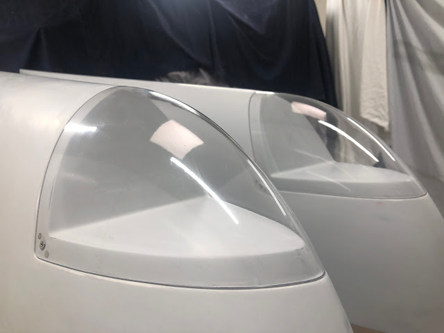
I elected not to install the nutplates for the landing light lenses until after all the sanding was done, as these may have gotten wet and gunked up with residue. So once the sanding was done, i drilled out the hole for the screw to #27, then countersunk the nutplate attach rivet holes using the permagrit 100 degree tool. I then managed to balance the wingtips enough to set the rivets using the DRDT2 tool - i know the tool is not designed to rivet, but i didn't want to use the rivet gun on the soft fibreglass just for nutplate attach rivets. The nutplates were installed, setting the rivets a little less than usual, then the lenses installed and the wingtips finally installed on the wings. 
The DRDT2 was screwed down so i could hang it off the bench to get access into the wingtips. 

I blocked up the lower die to allow me to reach the top nutplate rivets - without the washers the curve was too much in the top of the wingtip and i could not get a good angle.


With a fair bit of balancing, and the use of my ironing board 'bench' i was able to get the reach and correct angles to set the rivets. I used a ground down flat die on the top, so miss the landing light lens 'joggle'.

3 or 4 hands would make building so much easier.

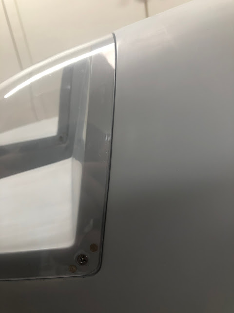
And here is the installed lenses - i am happy i took the time to add the micro and refine the interface of these lenses to the wingtip. They look semi-professional in my opinion. One of those satisfying builder moments which makes this so enjoyable an undertaking. 


Finishing up the Wing Kit! 

There was only a couple of small jobs left. Install the DIY Archer wingtip antenna, install the wingtips, install the aileron trim actuator, install the ADAHRS mount and finally the bottom skin access panels. 

A piece of PVC tube was added to protect the antenna and stabilise it inside the wingtip. I may need a larger piece of tube - we will see later on. 

The wingtips were installed using the hinge pins, and secured using a pan head screw.


Here are some photos showing the paint gap between the wingtips and the skins:

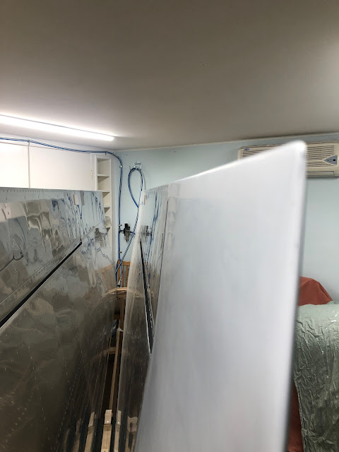
Happiness is an even gap.

The final job was to install the access panels into the bottom of the wings, including connecting the springs to the electric aileron trim unit and plugging it in, and placing the magnetometer shelf in position for safe keeping. Where the access panels will need to be open later (such as at the bellcranks, or to install the magnetometer) i just used 4 screws, and left a little bag hanging out with the remaining screws for that panel. 
I used cable ties connected a couple of rings down each spring to pull the springs together.


Which made it easier to connect to the motor arm. I then clipped the cable ties off making sure i didn't leave any in the wing bay.


I used some boelube on the flanges of the slide in ADAHRS shelf so the primer didn't stick (seize) over time.

Some old empennage parts were moved around...

...and everything placed into 'storage' in order to move onto the fuselage kit.

Some Wing Kit Stats

Overall i spent 524 hours working on the wing kit over 2 years, 6 months and 16 days. I shot 9,113 rivets, to bring the total at the end of the wing kit to 13,997. 

Sadly, of the 928 calendar days elapsed, i only managed to get into the shed on 268 of them, spending an average of 1.8 hours per day worked. 


I need to pull my socks up!