Search Build Log

Showing posts with label Proseal. Show all posts

1 Jun 2023

29-12: Initial Riveting of the Side Skins

The plans have you backrivet (on the bench) a few components to the side skins, before the skins are clecod to the fuselage sides for riveting. I decided that there were a few additional parts which could be backriveted to the skins, in addition to those called out on page 29-12. To make sure i wasn't missing anything, i clecod these in place and test fit the skin to make sure i wasn't about to do anything stupid! 

This is all the fuselage side skin components which will eventually be installed.

I separated them into left and right side piles.

The centre section side plate and upper drag fitting were back riveted to the skins.

I used my mini-backrivet set - which just fit against the side walls of the upper drag fitting.

Forward Stiffner is riveted only at the front

It's lovely when an area of such big rivets all get set and end up so flat.

Rear ribs are riveted only at the front to give flexibility for installing the aft fuselage in the next chapter

The canopy handle brackets and F01428 side frame were clecod in place

The forward stiffners were also clecod in place

The lower longeron was just balanced into position as you can't cleco this to the skin and then install the skin.


I also clecod on the arm rest - however decided this should be installed AFTER the skins are on the fuselage (see below).

Here i am explaining the order of operations for installing parts on the skins before placing the skins on the fuselage:

The only change to the above plan, was to leave the arm rests until after the skins were installed on the fuselage. This was because these ribs needed some heavy fluting (the skin in this location is very curved), and i was unable to do this fluting on the bench (with the skins flat). 
The arm rest ribs need to be left until the skin is on the fuselage. 

The last riveting on the skins was to install a single nutplate in each skin (it is a grounding point). I am unsure if i will need this (i don't think so) but it doesn't hurt to attach it at this stage. 
This bucking bar was made by my dad and has a hole which takes a standard squeezer die.

I then backriveted the nutplates to the skin.


Canopy Handle Brackets

Before committing to the above plan, i decided to test fit the canopy handle and found that the brackets were a little too close together, leaving the handle very stiff to operate. To fix this, i drilled out the lower bracket, installed the handle with all it's hardware, then riveted the lower bracket to the skin with the handle installed. This made sure the handle would operate freely. I guess, being dimpled components there is a little play in the holes, meaning the brackets went on slightly too close to each other for the handle to fit. 
The lower bracket was riveted with the canopy handle in place.

There is one rivet which is set in-between the 2 brackets which will interfere with the handle when the latch is closed. A small relief hole has to be drilled into the handle to provide space for this rivet. I should have marked this hole onto the handle before dimpling it however i did not! So to get the location for this, i put some torque seal onto the rivet, installed the handle and this transferred the location of the rivet to the handle. I then drilled a shallow depression for the rivet to nest into when the handle is closed.

As you can see i installed rivets into the 2 holes left over from the old rivet line (for the stock canopy latch handle brackets). 


Clecoing the skins to the fuselage

The skins were then slid into position on the fuselage and clecod in place. The upper drag fitting bolt was reinstalled (with TefGel) and I torqued the nut - i found the running drag on these nuts to be 15in/lbs. Looking up the torque table in Section 5 for an AN6 bolt i found the torque was 160-190 in/lbs. Taking the middle value (175 in/lbs) plus the running torque i did these up to 190in/lbs. 

Can anyone see the problem here??? 

As i was writing this blog, i realised these bolts and nuts are AN5 bolts and AN365-524 nuts. NOT AN6 (the lower drag fittings are AN6). Looks like i will be undoing these nuts when i get home from work today and redoing them to 140 in/lbs. Oops. The value of review in this blog has just been demonstrated! 


Getting out the black goo once again!

When clecoing on the skins, the plans call for the use of some fuel tank sealant to seal the seam between the firewall and the side skins, however it also calls for some fuel tank sealant along the forward section of the side skin where it lays down on the upper longeron. The sealant at the firewall is to prevent noxious gasses etc entering the cockpit in the event of a firewall forward fire, so for this i will use the 3M FireBarrier 2000+, as i have done previously. However, the tank sealant laid down horizontally along the skin edges (along the upper longeron) i can only assume is there to prevent water ingress. Since the 3M sealant is a silicone based product, and the side skin will need to be painted, i decided to use fuel tank sealant for the horizontal skin seal against the upper longeron. 

Which meant it was time to break out the black goo again! (i actually had to buy another can - this stuff is expensive - hopefully this is my last can). 

I held the skin away from the fuse using wooden blocks.

And masked up the areas where didn't want the proseal to end up


I then applied the 3M Firebarrier 2000+ to the firewall flanges, making sure to seal all gaps between the rib notches in the firewall sheet. 


I cleco'd every hole and will let the sealant set up for a day before riveting this section.

I made sure to seal off all areas where water ingress could occur.

I also sealed off all areas where noxious gasses could pass from the engine compartment to the cabin.


Next up will be to actually start setting some rivets in the side skins! 


11 Feb 2021

18-09: R Fuel Tank Leak Repair

Well, this was a bit of a journey, but i will try and logically lay out the steps i took to repair the leak in the right tank. 

Cause

The first comment is what i believe to be the cause of my issues - when i was placing the baffle down, it was aligned such that the baffle was hanging over the root end of the rib (where the leak ended up) by perhaps a quarter of an inch. I did not do a good job aligning it with my fingers when i dropped it down into place. I did not think it was a good idea to lift if off again, as it had come into contact with all the carefully laid down sealant beads, so i just pushed it gently outboard to align all the holes. 

This meant on the root end, i was pulling the bead at that end (which had stuck to the web of the rear baffle) away from the end rib flange. It is my belief that this is what caused my issues - so for anyone following, make sure you extend your fingers and align the baffle with each end when you drop it down

1st Try

As mentioned in this post there was a small open section in the sealant which was in the same location as where the leak was, so i made an assumption that there was probably where the leak was stemming from. 
I believed this to be the offending location

So i had to cover this area with sealant. Luckily, this was quite close to the location of the fuel sender hole - so i removed the sender screws and cut the sealant bead around the sender flange with an exacto knife. I then used a pallette knife to gently pry the sender out of it's bead of sealant. 

Once it was off, the sender, the rib flange and all the screws and lockwashers were all cleaned of sealant using scrapers, a toothbrush and acetone. 

In order to ensure that any additional sealant would stick, i used a rag soaked in acetone on my finger to get clean the existing sealant. I was able to reach this area with my finger. 
A piece of aircraft canopy made into a scraper

The sender after removal

The offending area after cleaning up with acetone. 

Once this was done, i applied as much sealant as i could to this area. I found the easiest way was to just put a blob on my finger and squeegee it into place. 

Here you can see the location of the additional sealant and how it has definitely covered the offending location. It was spread along the flange as far as i could reach with my finger in each direction. 

2nd Try

After 5 days to let the sealant cure, i set up the manometer again - and she STILL LEAKED in the same location as before. The manometer was showing a solid leak. 

I was honestly surprised and confused at to how this was possible. I decided to get the borescope back into the tank to have another look. The only section which was still exposed from the original sealant application was in the corner, adjacent to the fuel drain location. I was unable to get sealant into this area the first time around because my finger didn't reach. 

So i had to get creative - in order to clean this area before further sealant application i bent a plastic toothbrush handle using the heat gun, and was then able to get inside to clean this area. To actually apply the sealant, i was able to snap a tongue depressor in 2, and tape it to the end of my finger. This allowed me to get to the corner to smear sealant into that location. 
Using the bend toothbrush to get into the corner.


The fuel sender was cleaned up again, sealant reapplied and the tank closed up. Fingers crossed once more. 

3rd Try

After 6 more days to cure, i came back to the tank and was AGAIN distressed to see that the tank was not holding pressure. However, this time the leak was not in the same location along the rib flange - it was leaking out of the flange of the fuel sender!!! 

I must not have sealed this correctly. So, time to remove it again! 

It was resealed properly this time after a good cleanup of all the flanges and the screws. 
Sealant is applied to the rib flange

The screws are ready to go with Loctite 565

I remade the sender ground wire as the locknuts had damaged the terminal after no many repeated installs. 

The sender installed (hopefully for the last time). 

4th Try

Finally, after 4 more days to cure, i went back to the tank and set the test up. THE PRESSURE SEEMED TO BE HOLDING! 

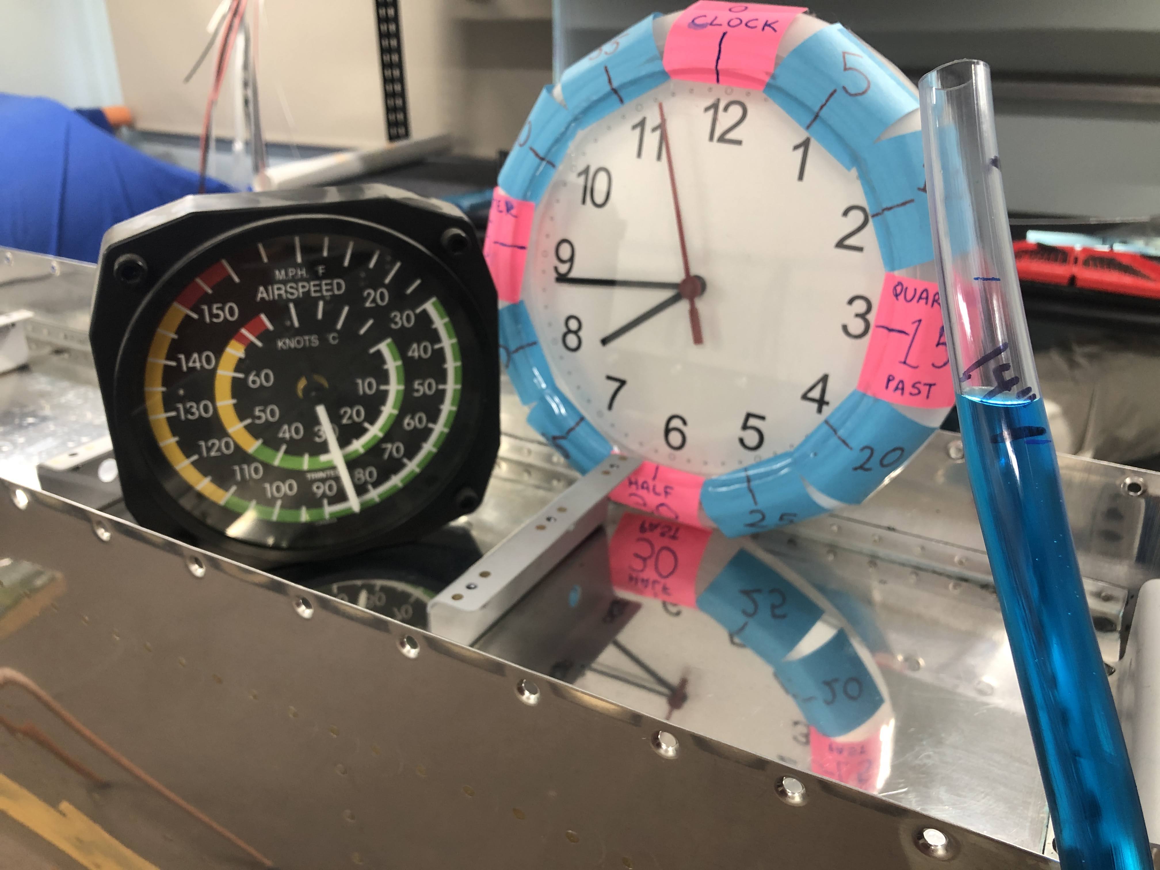
I left the tank for a while to make sure it was all ok, but the temperature in the shed was increasing that day and the manometer flowed over - in fact, it squirted blue liquid all over the walls and the storage shelf, staining my left wing top skins! (doh). Not to mention a big blue stain on the carpet. Oh well. 

I waiting until around 8:45 PM and setup the manometer again. 
8:45 PM - 30c and just above the line. 

Came back the next day:
7am the next day - 21C and the level has dropped a lot. 

9:30am - temp has risen to 23C and the level has risen

10:30am - temp is now 25c and the level risen even more.

11:30am - temp now 26C and the level still rising

12:10pm - now 28C and not quite up to where it started

12:30pm - 27C and up to the same level.

It should be noted that the water level got back to the same level as where it started, but the temp was 3-4C lower than the starting temp. During this time there was about a 3HpA drop in atmospheric pressure, so i assume to accounted for the additional help to rise back up to the line with the lower temperature. 

Having said all this, i am happy to confirm that FINALLY:

Postscript

Ever wonder what the 1psi does to the tank during testing? I was surprised how much flex the tank has. This was taken at the point in the video above right before, then after the manometer flowed over and released all the pressure: