After a long time between sessions, i finally finished up the HS in only 2.5 hours. I don't know why i lost my confidence and waiting to put the rear spar in (and a landscaping project and new shed build didn't help with my spare time) - in the end i should have been confident my riveting of the ribs was fine - i checked every single rivet and they all looked ok.
So - BUILD ON!
The rear spar started by riveting the rear spar to the ribs using LP4-3 pull rivets. The tip ribs and the inspar ribs were completed with AN470 rivets - all done with the squeezer, except the middle 2 rivets of the inspar ribs (couldn't reach with the squeezer). These were done with the gun and bar.
The next step was the final assembly of the HS - it was a long road to get here (almost 50 hours of work), but this gives a great sense of satisfaction to get this far!
The manual called to rivet the nose ribs into the skins first. As the skins were flexing out quite a bit, i used tape on the top of the skins to help hold them together (taping them the same width as the rear spar), and used a homemade "wire clamp" to squeeze the skins in toward the top of the nose ribs.
"Wire Clamp" from the outside. You just twist the wire ends like this to adjust the clamping pressure.
When i was at Narromine, my TC, Peter Pendergast showed me a lot of RV-14's, and pointed out the large impressions left around each of the rivets on the empennage (and HS especially). These were all about maybe 1" in diameter, and were little concave impressions around each of the rivets. He told me this was due to the air pressure being too high when riveting; the pressure of the gun actually deforms the skin and underlying rib when the rivet is being set. So i decided this was a goal for my build - to get this right. In some cases when this happens, you can hit it from behind to push the dent back out - but not in the case of the HS (as there is not enough access).
My rivet gun came with what i thought was an "air regulator" on the gun, like this one:
I set this to #2 on the gauge and began riveting in the nose ribs. Each time i set a rivet, i was checking to see how much deformation there was on the skin / ribs. As you can see, there was a lot of deformation occurring - just like the completed aircraft i was shown at the airshow.
I had a chat to Pete, and he recommended removing the "air restrictor" from my gun, and simply setting the shop regulator to a lower pressure. I looked around on the google forums, and found a pressure table for various rivet sizes. I started with these settings, and i was quickly able to work out what was working for each rivet size. I like this method, and it has improved the riveting a lot i think.
A much better result once i used the regulator to control the gun pressure.
I have already dropped a bucking bar into the skins once, so i made sure i used some rags just in case. This photo also shows the little plastic tube i have been using on the rivet tails sometimes - where there is a rib flange that is sitting off the skins (like in the image below), i use the tube on the tail as i can then push on the bar to push the flange toward the skin. I leave the tube a little longer than the rivet tail (using the rivet gauge to measure and cut it), and once the rivet starts to push out of the hole, i stop it pushing out with the mushroom set of the rivet gun. I then maintain this pressure balance until the rivet starts to set, and then release a little of the bar pressure. Most times the rivet won't set fully - so i remove the tube, and set it a bit more. This usually results in a rib flange being nice and right against the skins.
A close up of the plastic tube on the rivet tail, before bucking
I then put the whole spar and rib assembly into the skins - this thing is HUGE (and heavy with all the clecos in it).
Next, I riveted this using LP4-3 rivets to the nose rib flanges. After the dints i got in the skin of the rudder from using a crappy cheap rivet gun, i purchased a very small Kinchrome rivet gun. This thing is great, fits in tight places, and doesn't jump a heap when the rivet stem breaks off. I made sure i added cardboard to protect the skins just in case.
I also had a little visitor into the shop, who signed his name on the forward spar to posterity!
Next up i riveted the spar to skin rivets, then the rivets from the spar back to the stringer, then the stringer itself, and finally the rivets between the stringer and the trailing edge.
Almost all the rivets were set with the gun and bucking bar (using a wooden spacer on the bar), but i used the squeezer in any place where it would fit (the end ribs etc).
I am really happy with how the rivets are turning out - the rivet lines are looking nice and flat with none of the aforementioned deformations.
There were a couple of tricky rivets on the inspar ribs, which were hidden behind the flanges of the stringers - you literally can't see these rivets at all. I just placed the bar as best i could using feel, and then riveted them. I then checked them with a mirror and a torch. Overall, i am having a good run on these rivets - only maybe 10 had to come out. I have been drilling them out as soon as they set, so i don't forget or miss any.
The final step once the skin to ribs were finished, was to remove the assembly from the cradles and lay it flat on the bench. There were 5 rivets per side left to do - the AD4-7 and AD4-8's which connected the modified inspar and nose ribs to the spars and spar doubler. This is one thick bit of kit and these were very long rivets. I started out using 40psi on the regualtor, and quickly realised that i needed more. I was using the offset 6" cupped set on the forward side (manufactured head), and the bar on the back side, wedged in against the ribs. I used some cardboard to prevent scratches. These were some tough rivets! At 60psi they took about 3-4 seconds to set - the whole assembly was walking across the bench. For the most part, the rivets are just acceptable. A couple are very slightly bent over, but given the thickness of the material, and how hard they would be to remove, i have elected to leave them in.
On the left side, i clipped the middle rivet tail with the bucking bar when i was bucking one above it - This damaged the shop head slightly as per the pictures below. I spoke with the TC, and we both agreed that the rivet will still do it's job with this small error, and the chances of me destroying the hole in the spar and doubler are high - so we elected to leave it alone.
The bucking bar just clipped the middle rivet.
These are the 5 modified ribs / spar rivets
These are the 5 modified ribs / spar rivets
As you can see this is one large bit of aircraft! At this stage, all that is left is to rivet in the rear spar. I am toying with the idea of waiting until a TC can have a look inside the assembly, before i go ahead and rivet. I think i will leave it a few days, then inspect the rivets again and make the final decision as to if i wait or not. I am tending to think that all is good in the world at this stage and i should just finish it off - but not 100% on that decision.
Moving on, it was time to dimple all the ribs of the HS. As already mentioned, I decided to prime them first before dimpling them and i tested this on the nose ribs which worked great. After only 24 hours, the inspar ribs held up to the dimpling with no problem. Some of the ribs had holes which are not dimpled (as these will take nutplates for the empennage fairing waaay down the track) and these were covered with tape.
Once the ribs were complete, i moved onto the skins. This involved deburring the edges of the skins using the vixen file, edge deburring tool, sandpaper and scotchbirte. The holes were not deburred with a tool (as they are punched to final size), however i scuffed them both sides with a scotchbrite pad. I then cleaned the skins outside on the table using EkoClean, followed by etching with EkoEtch and mechanical scuffing. The skins were then dried and primed.
skin deburring
Cleaning and etching the skins.
Whilst the skins were drying, i moved onto riveting the stringer and web assembly together. I firstly riveted the ribs to the end flanges of the stringer web using a gun and bucking bar. I think i had the pressure set too high, as the ribs deformed a little bit where the rivets went in. Thinking it was ok, i moved onto riveting the web to the stringers using the squeezer, and this went fine. Once i was done, i really wasn't very happy with the deformed ribs - the more i looked at it the more i didn't like what i was seeing - the poor workmanship was bothering me. I drilled out the worst 2 rivets, and tried to re-rivet them together, however the ribs were deformed and i could not get the web flanges to sit flat - so out came the #31 drill bit and i drilled out all the stringer web to stringer rivets. Once the stringers were removed, i could then remove the rivets between the stringer web flanges and the ribs and start again!!!
Shouldn't have used the gun on such thin parts - or should have turned the pressure down to 20psi!
First i gently removed the bend in the rib webs using a hammer and and spoon and straightened the flanges of the stringer web with a hand seamer. I then did what i should have done all along, and used the squeezer to re-rivet the stringer web to the ribs, as well as the web to the stringers. Happy i did this rework, as it really was bothering me.
I think my reluctance to use the squeezer was due to the issues i had on the VS rear spar. I just couldn't get a rivet to set straight - it turned out the yoke was flexing too much due to the Cleveland quick release pins. Once i tightened the yoke onto the squeezer the tool worked a lot better. The use of a bit of tube over the rivet also helped keep the flanges flat onto the rib.
These were done with the squeezer and are a lot better.
The other thing to note relates to the little tabs which rivet the ribs to the stringers. Because the 2 modified inspar ribs are at an angle, the tab is rotated against the stringer, and contact the stringer at it's bend. I had to file back those tabs (respecting edge distance) to stop the little tabs interfering and rubbing on the stringers where the internal bend is.
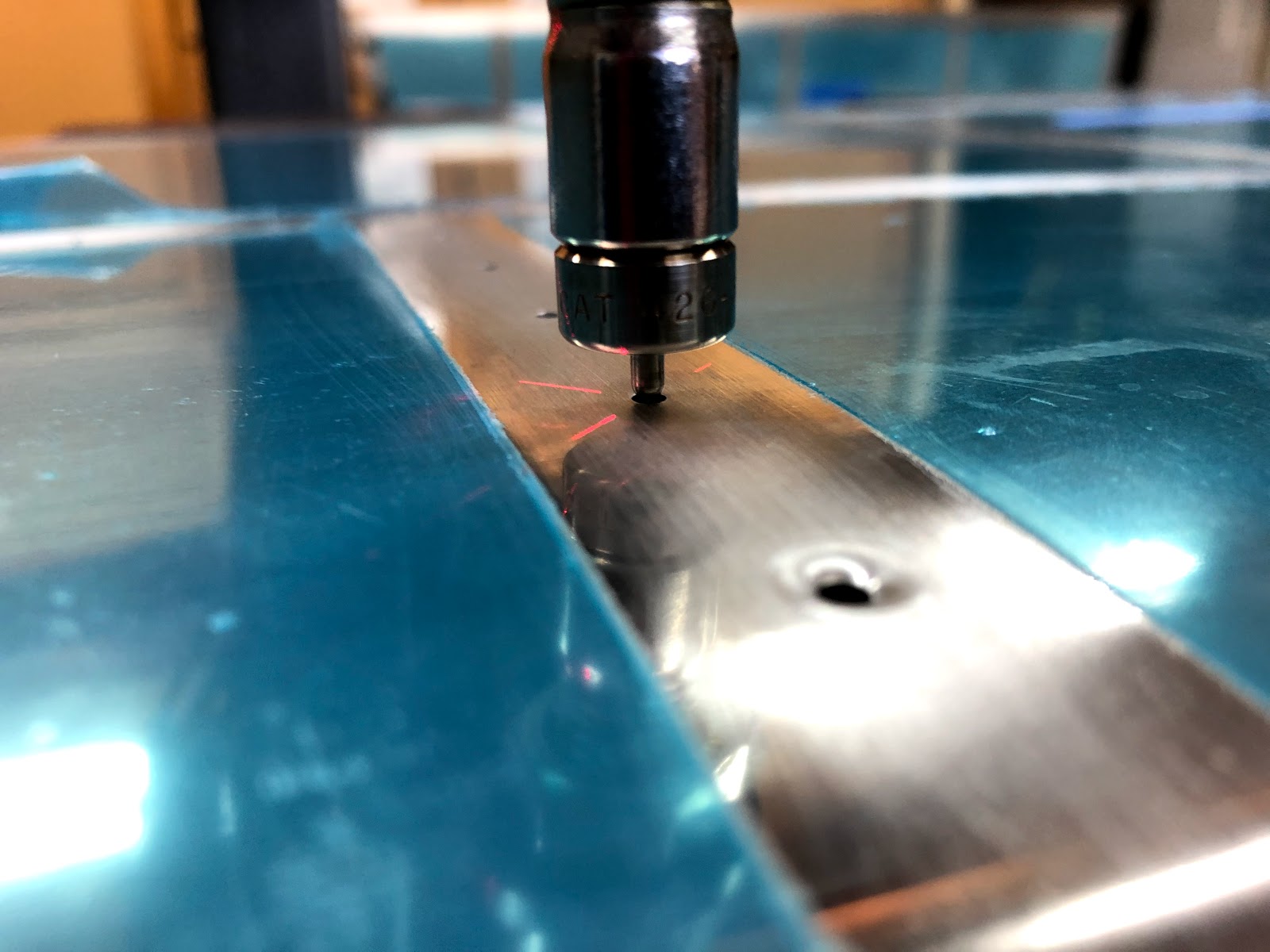
Once this section was complete, i moved onto dimpling the HS skins. I read a lot of people had to remove the handle off their DRDT2 to get it to fit inside the skins when dimpling near the nose. I decided to put the female die on the bottom and the male on the top, and was able to maneuver the skins over the edge of the bench and the 2 portable dimpling support tables i made up. I used a laser pointer to align the die and went slowly.
Nice Dimples!
I even had a great helper in the shop for the dimpling!
Moving on, i went ahead and riveted the inspar ribs to the forward spar using the squeezer.
I completed the deburring of the edges of the inspar ribs, and installed the remainder into the structure to check everything fitted ok - was cool to see how it all lined up:
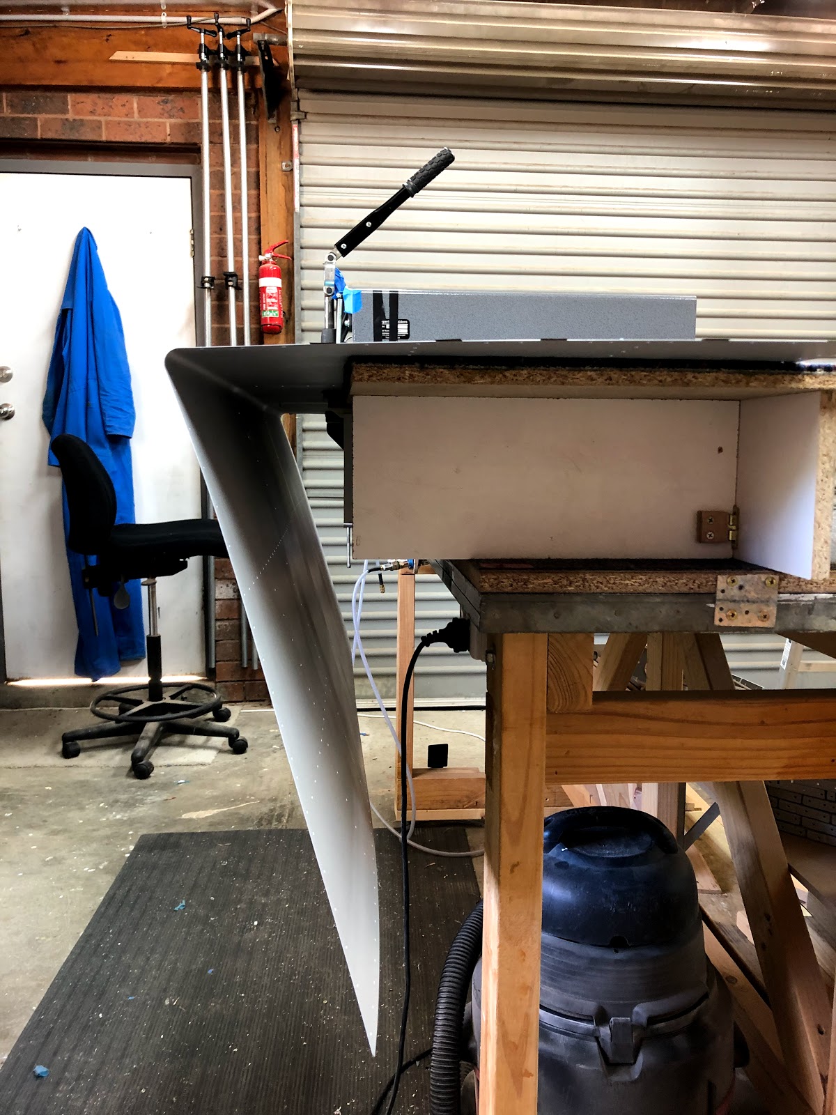
I then unclecod everything, and removed the skeleton from the assembly - this thing is BIG!
I decided that this time around with the ribs and skins, that i would try and dimple after the priming had been done. This allowed me to clean, etch and scuff each part without having to worry about the dimples. I was finding it hard to scuff inside each dimple (where you really want the primer to stick), and the backside of the dimples were destroying the pads and making it hard to scuff.
I figured i would start with the nose ribs - and prime these first as a test, to see if the primer would hold up to the dimpling process. The parts were left about 2 days before dimpling.
Dimpling was done with the pneumatic squeezer, and the Cleveland Sub-Structure Dimple dies. I ground one side of the female dimple down, so it did not hit the flange bend radius of the ribs. It seemed to work great, and there was no damage to the primer whatsoever. Not bad for a water borne product - i am starting to really like working with it.
A dimple...
I used the 0.025" #40 test coupon to see how the dimples fitted - and was happy with how they were sitting.
Once this was done, i was happy to go ahead and prime the rest of the inspar ribs, and i will dimple these after priming. I think i will also do the same to the skins - the primer may even help protect the inside of the skins against scratches from the DRDT2.
Parts have been cleaned, and are being scuffed and etched...
Parts have been scuffed and etched and are ready for priming in the booth. I dried them using heat lamps.
I used some scrap PVC pipe i had to make a hangar which hangs off a nail and is removable in the booth. This is to prevent the part flange edges sticking to the wet paint on the wire and leaving very small marks of exposes aluminium on the flanges. This worked very well.
Here's a time lapse of the inspar ribs being primed in the booth...
...and the final product, ready for dimpling. It's cool how pieces of aluminium become aircraft parts once they are deburred and primed; very satisfying.