Search Build Log

Showing posts with label Tools. Show all posts

4 May 2019

11-04: Elevator Trial Fit

Rod End Bearing Installation

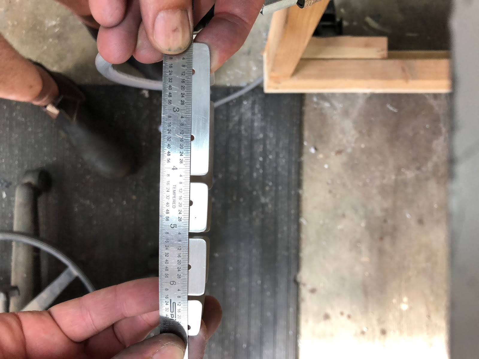
Once the leading edges were rolled, i installed the rod end bearings using my PVC tool i made earlier. The tool ended up breaking after a few tries, as the inside tube edges had been worn away, so i ended up using a pair of smooth jaw parallel pliers to gently screw it in.

The plans call for you to install the bearings 13/16" from the spar face, so i used a ruler with a piece of tape at 26/32" to set the middle of an AN3 bolt at that distance.
I have some nifty pins my dad made up for me based on something we found sold by Cleveland, and I used these for the trial fit of the elevators:


The pin is inserted, then the aluminium "nut" is removed. The pin is sized to match an AN3-10 bolt, and the threaded tail is designed to fit inside the skins, so it does not interfere when moving the control.
 

The pins worked well, but i noticed there was a little bit of play, so i thought it would be better to just install them using the called out hardware - AN3-10 bolts. Getting these is however is a little difficult, so i used some scrap and made up a 'don't drop the bolt tool'™:
:


The second bend at the 'handle' end really helps to maneuver the bolt into position more easily.
 

Elevator Rubbing

Once the elevators were installed, i checked the amount of throw i was able to get. According to the manual, it needs to be +30 degrees, and -25 degrees. This was checked by holding the elevator counterbalance level with the skins and zeroing out the iphone level, then moving the surface.

Unfortunately, i was unable to get to the full throw, before the elevator leading edge skins began to rub on some part of the HS rear spar. I got to about +25 and -20 when the rubbing began and i could feel the skins binding. In order to work out where this was, i removed the elevator and placed some blue tape on the area. I then added some chalk to the areas i thought might be the cuplrit and moved the surface until i felt it binding, then checked for evidence of chalk on the leading edge.
Tape added before the chalk was applied

The areas of rubbing can be seen between the 2 lines:


What to do next?

Given the rubbing experienced above, i decided to scrap both elevators and start again...

NOT!

I figured i had 2 options here - the first was to try and reshape the leading edges with a rubber mallet and with my hands to try and stop them rubbing so much. The second was to wind out the rod end bearings a little - but how far can i wind them out?

Unfortunately i was unable to see inside the HS at this time to see how many threads are showing out the back of the nutplates. Instead i reverted to the forums, and ultimately the RV7 manual, which has the following helpful diagram:

Given the RV7 uses the same rod ends, and the same nutplates, and the material is about the same thickness, i figured that i could safely wind the rod ends out to 7/8". I have contacted Van's to check that this is acceptable, and i am waiting for confirmation. Whilst i am waiting, i decided to trial fit the elevators once again, after winding the rod ends out, and after massaging the leading edges somewhat.

See HERE for a post on where i ended up with the rod end bearing distances.

Success!

The combination of the above actions seemed to have worked. To check it all out properly, i skipped ahead and made the spacer block for the elevator horns shown at page 11-04:


I then clamped the counterbalance arms against the skins, so the elevators were "in trail":


With the elevators 'in trail' i was able to compare the 2 elevator horns - in my case they were fairly close together:


I placed a string line in the centre of each trailing edge, a little in from where the ends taper, to check for straightness. I found that for the most part, the elevators were straight, however both inboard ends were around 1 trailing edge diameter "low". They seemed even however, so i guess this is just the build up of tolerances in the build of the elevators and the HS. Each elevator as previously noted was straight in itself, so likely this is the mounting of the elevators on the HS. In any case i don't think this will cause major issues when flying.
Right tip end

Left tip end

Left root end

Left tip end
I was then able to install the spacer block, and clamp the 2 elevator horns together, and remove the clamps from the counterbalance ends, and finally measure the amount of travel i was able to get with no binding. It turns out i can easily get the required travel (+30 and -25) with zero rubbing, and i can in fact to go +35 without any rubbing at all. I can get -26 when one horn contact the lower portion of the HS spar.
Required upward travel

It goes to here without any rubbing

It stops here and is contacting the HS hinge brackets, but is clear of the skins. Ultimately the upward travel of the elevator will be controlled by the angles on the aft fuse deck - so i might even end up taking them to +35 - but that is waaay in the future. 

This is the maximum lower travel

~~~

20 Nov 2018

8-06: HS Rib deburring and a homemade Flanger™

Page 8-06 is one of those pages that begins with a very simple statement:

A small statement leads to MANY MANY hours of work! This step included 8 nose ribs, 6 inspar ribs with no stringer holes, 6 inspar ribs for the stringers, and a stringer web! The inspar ribs with stringer holes were especially time consuming.

The most ribs in one section so far...
The task started with setting up the skins in their cradles - i decided that as i finished each rib, i would cleco it into the skins / structure to check that all was well with the fluting and shape of the ribs. I began by deburring the nose ribs, and rounding off the front radius' such that they would not create a dint in the skin near the nose:

The cradles were screwed to aluminium saw horses to give stability.
A couple of the nose ribs had their end flanges angles adjusted so that when they were attached into the angled part of the skin, the rear flange would sit flush against the front spar (this was checked once the front spar was put in place in the structure to make sure the angle was correct). Each rib was checked to make sure that the holes aligned. Each rib had it's flanges bent with a hand seamer make sure they were 90 degrees to the rib web, which tool a lot of times and repetitive iterations (a new tool to do this later!!)
Rear rib flange bend to 10 degrees
All holes are aligned. 

Nose ribs in place in the skins.
Nose ribs in place in the skins- the root rib end flange looks about right.
Front spar cleco'd in place. 
Very satisfying when everything lines up!! 
As mentioned above, for each nose rib i had to use a square to check the rib flanges, then put that down and adjust with the hand seamer, then re-check each flange. This was fairly time consuming, so i ended up biting the bullet and creating a flange bending tool as built by many others. This works a treat, and i can now straighten the flanges of a rib in around 20 seconds. I elected to screw the tool to the work bench to stop it moving around - i can easily unscrew and re-position as required. 


Two of the inspar ribs needed to be modified so that they flt in the angled part of the skins. I bent these as per the instructions, however then clecod them in place into the skins and hand bent them so they sat properly and there was no stress on the part. 

Next, I continued to deburr the edges of the inspar ribs. The process went something like this for each rib, and takes perhaps 15 minutes each rib:
  • Smoothing the rib flanges using the scotchbrite wheel on the bench grinder (being careful not to catch the edge of the wheel on adjacent flanges). 
  • Using an electric drill and a aluminium oxide flapper wheel to smooth the edges of the lightening holes. 
  • Using small flat and round mini files to clean up any major bumps (like where the cutouts for the stringers were - there were a number of 'teeth' on these from the stamping process). 
  • Using 400 grit aluminium oxide paper, folded in half around a scotchbrite pad to smooth any large gaps in the flanges, such as the corners, or the large gap where the stringers go - i find this conforms to the large gap very well, and gets the job done much faster then just paper alone. 
  • Using 400 grit aluminium oxide sandpaper bend around an old hotel room key card, to get down into the bottom of each flange cutout. 
  • Usign 400 grit aluminium oxide paper folded in half to do the edges of each rib flange cutout. 
  • Running a scotchbrite pad over all flanges and the lightening holes, inside and out, to smooth any remaining scratches etc, and also to deburr the pre-punched holes. I also run the pad over any holes in the rib webs to deburr these also. 
  • Finally, I use a standard deburr tool to deburr any other holes (like tooling holes etc).
Once this was done for each rib, I used the flange bending tool to ensure that the flanges were all 90 degrees to the rib web, then checked the rib was flat. If a rib needed fluting to sit flat, i did this also (however found that because of all the cutouts in the inspar ribs that nest into the stringers, none of these needed fluting; just gently massaging to align with the holes). 

I then clecod the rib into the structure to give me some feeling of satisfaction and to keep the motivation going!!! She is SLOWLY coming together! 
Ribs in place.
 

Slowly starting to run out of clecos!
Stringer web in place (without the stringers at this stage). 
Not many to go now!!! 

Lots of sandpaper is used up, as well as scotch brite pads.