I decided that i was not a fan of the Van's method for attaching the wingtips - namely, using nutplates and screws. Partly due to the maintenance issues with removing all those screws (and their tendency to cam out and look average), partly due to my experience with screws in fibreglass (they worry and wear and eventually need tinnerman washers), and partly due to the puckering you can get with an older fairing.
 |
| This is what i am going for. |
The alternate method is to use a couple of hinges on the top and the bottom of the ends of the wings. The wingtips are held in place using the hinge pins, which are then retained so they don't slide out. To remove the wingtips, you just pull the 2 hinge pins and pop the wing tip off - and there are no visible fasteners.
The pioneer in this regard was Mike Bullock, with his RV7 who did a fantastic write up on the method. I plan to follow this method closely. There are a few changes which need to be made to the method - mostly the alteration of the end rib (on the rv-14 it interferes with the top hinge by about 4 eyelets, and on the bottom by 1 eyelet). I liked the approach taken by Carl & Rafael - so i copied it blatantly!!!
Drilling off the hinges to the Wing
The hinge method uses a wider AN257-P4 (MS20257-P4) hinge on the wing side, and a thinner AN257-P3 (MS20257-P3) hinge on the wingtip side. I ordered 2 x 6ft lengths of each hinge. The reason for this will become clear soon enough, but it is so you don't the gaps in between the hinge eyelets right under the edge of the wingtip.
Step 1 was to add additional holes between the existing holes in the ends of the wing skins - the existing holes are designed for a screw pattern, and you need more rivets than you do screws. I used a rivet fan and carefully match drilled the holes - carefully, because the existing holes are not of a consistent spacing.
 |
| In the corner i added a hole aligned with the existing rivet pattern. |
Step 2 was to take a P4 hinge, and match drill this to the wing. I made sure to have an eyelet at the end of the skin on the top and bottom. I drew a line on the hinge which was at the required 3/16" edge distance for an AD3 rivet, and aligned this with the holes in the skin and clamped the hinge in place. I then match drilled every 2nd hole starting from the trailing edge and working my may forward.
 |
| Line drawn 3/16" in from the edge of the hinge. |
 |
| Clamped in place ready for match drilling. |
 |
| Match drilled to the wing. |
Modifying and installing the Trailing Rib
On the RV14 there is a trailing rib which is installed into the ends of the wingtip, to give structure and shape to the wingtip where it is not supported by the wing skins. The plans have you install it so the flanges are outboard (leaving a flush surface).
Since the wingtips will be secured with the pins between the hinge halves, we need some space to install and remove these pins and to secure them from falling out. The solution is to use the left trailing rib on the right wing and vice versa. This leaves the web of the rib outboard and gives you the space for the hinge pins.
The issue is that the rib now interferes with the bottom hinge by about 1 eyelet, and the top hinge by around 4 eyelets. The rib needs to be modified to fit. The process i used to make this modification is as follows:
Step 3 I cleco'd the wingtip in position on the wing and selected an arbitrary position on the aileron and drew a line which i carried over to the wingtip. This line is used to take a measurement of the thickness of the aileron at that position. I then slid the rib into position inside the wingtip, and made sure the corresponding position on the wingtip was the same thickness. This set the correct location for the rib, and i was able to clamp this in position. If it were located too far aft, or too far forward the wingtip would be a different shape to the aileron.
I then marked the location of the rib flanges onto the wingtip, and marked the rib location so it could be installed back in the same position. I also temporarily placed the hinges in position and marked roughly where they were located.
 |
| This measurement.. |
 |
| ..had to match this measurement. |
Step 4 With the rib flange and hinge locations marked, i was able to transfer these marks to the outside of the wingtip and mark out a hole pattern for the rivets which will hold this rib in place. I did not mark any holes where the hinges interfere with the rib (and where the rib will need to be modified). Holes were drilled in the wingtip, then the rib was placed back into the same position it came from (using the reference marks), and i clamped and matched drilled this rib to the wingtip.
 |
| A rivet pattern was laid out and drilled onto the wingtip. |
 |
| The rib was match drilled to the wingtip. |
Step 5 Now that the rib is in it's final location, i was able to work out where the rib was interfering with both the wing side hinge (the wider P4 hinge), and also with the wingtip side hinge (smaller P3 hinge). I did this by placing the hinges together with the pins and placing them into the wingtip.
The following modifications needed to be made:
BOTTOM
Only a small amount needed to be cut off. I removed about 1/2 - 3/4" along the bottom of the rib in the corner. This didn't appreciably affect the strength or function of the rib.
TOP
The top was a whole other story. The larger P4 hinge overlapped the flange of the rib by about 3.5-4". I was able to place the wing side P4 hinge in place, but there was no way to place the wingtip side P3 hinge in place without removing the whole flange. I was not a fan of this idea, as I felt the rib would lose a lot of strength. The solution was to cut the wingtip P3 (thinner) hinge shorter to clear the rib, then use an offcut piece of the wider P4 hinge to make a 'bent hinge' arrangement which fastened to the trailing rib itself (sounds complicated i know).
The idea is that instead of the wider P4 wing side hinge meshing with the thinner P3 hinge riveted to the wingtip, for the last 4-5 eyelets, it would mesh with a piece of hinge which was bent at a 45 degree angle and attached to the web of the trailing rib. A small angle bracket would be placed on the other (outboard) side of the rib to give some further support and to stop the rib moving inward / outward when installed. It is harder to describe that to see in pictures, so here goes. (This idea was stolen totally from
Carl & Rafael)
 |
| Here you can see how the top flange of the rib was modified. Almost all of the flange was removed, with about a 1/4 remaining for support. Basically, i removed as much of this hinge as i needed so it did not interfere with the wider P4 hinge which will be attached to the wing. |
 |
| This shows where the flanges used to be! |
 |
| This shows the modified rib in-situ with the wider P4 hinge in place. The eyelets outside of the rib location will mesh with the thinner P3 hinge which is riveted to the wingtip. However, i could not continue this piece past the end of the rib without having to remove the whole rib flange. Instead, i removed only enough to clear the wider P4 hinge. This left a 1/4" ish wide 'foot' on the bottom of the rib to give a solid support and make sure the vertical dimension of the wingtip remains correct. You can see here i am holding the offcut piece of P4 hinge which will be trimmed, bent and riveted to the rib. |
 |
| I tried to bend the hinge like this but it didn't work - my bender was too wide for the width of the hinge and it just bent the eyelets. |
 |
| What worked much better was to clamp it between 2 bits of plywood and use a calibrated bash with a hammer! |
 |
| Here you can see how it works - the wider P4 hinge which will end up attached to the wing, meshes with the small piece which is bend upward and riveted to the web of the rib. |
 |
| This was the match drilled to the rib. |
Now this method works pretty well and my plan was to bond the rib into place in this location. To give a better bond, i decided (using Carl & Rafael's method) to bend up a little angle bracket which will be riveted to the back of this rib using the same rivets as the bent hinge. This will give more surface area for bonding and more support of the rib inboard / outboard (likely only an issue when installing the wingtip).
 |
| Here is the angle bracket. It was match drilled to the lower wingtip surface just for holding in place for test fitting and when bonding. I will not rivet this in place, just bond it, as rivet access will be too hard here. |
 |
| The angle bracket is on the left, what remains of the original rib flange is in the middle. These will end up being a good bonding surface. The the load is taken by the hinge on the right. |
Match Drilling the smaller hinge to the wingtip
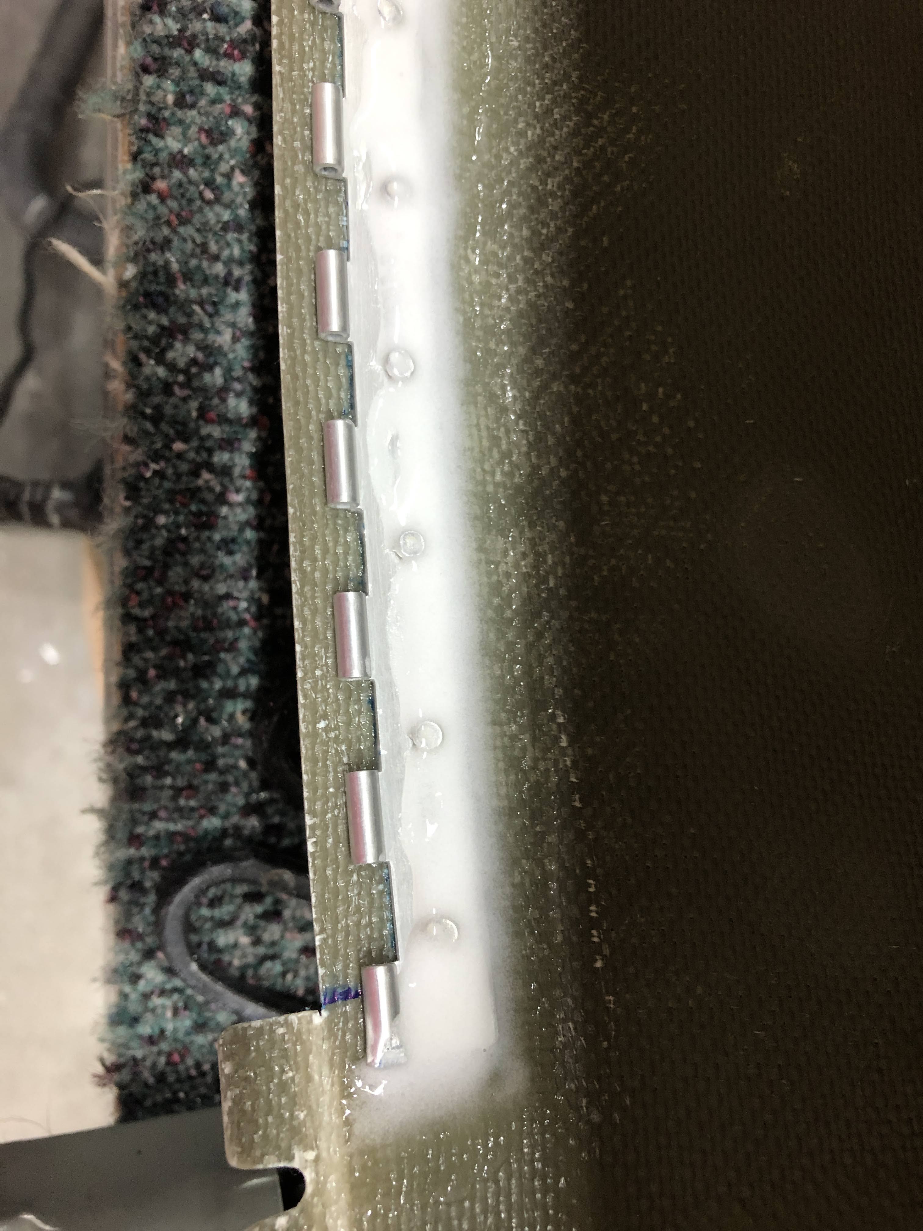
Step 6 The wider P4 hinge will mesh with a smaller P3 hinge which is riveted to the wingtip itself. To do this, i drew a line down the middle of the smaller hinge and used the hinge pin to put it next to it's partner (the wider P4 hinge). I could then copy over the hole locations from the wider hinge to the smaller hinge, and i drilled these to #40.
Since the rib was modified, i was able to cleco the wider P4 hinge to the holes in the wingtip and put the smaller P3 hinge in place using a hinge pin. It was then a fairly simple task to match drill the hinge to the wingtip using my 90 degree drill.
I made sure the smaller wingtip hinge had one eyelet at the end, and squashed the end of this eyelet to give a positive 'end stop' for the wing pins when they are installed.
 |
| The smaller hinge was match drilled to the wingtip and i celco'd as i went. |
The BIG CUT!
So, these hinges are all match drilled in place, however the wingtip won't be removeable unless i split the wingtip at some point between the 2 hinge pieces! I wondered where this cut should be and
pondered making it under the wing skin itself, however the most logical location was aligned with the edge of the wing skin. To do this, i marked on outside of the wingtip where the hinges ended so i didn't cut too far - the wingtip will retain it's flange where the nose section is located (where there are no hinges).
Step 7 I could then cleco the wingtip in position on the wing and i used my Japanese pull saw with a 1/64" kerf to scribe a line along the edge of the wing skin. Once i thought i had a nice positive line, i used a mechanical pencil to darken up this line. The wingtip was removed and i used the saw to cut off the flanges at the marks! This worked great and i've got a beautiful straight line.
 |
| Finally! Wingtip held in place using the hinge pins |
 |
| Aligned nicely! |
 |
| The aileron and wingtips top surfaces stayed really well in alignment. Very happy. |
 |
| Trailing edges are aligned very well. They didn't move a whisker. |
 |
| I used this opportunity to mark where the trailing edges of the wingtips will need to be trimmed to be level with the ailerons. |
Final Steps
This post has covered the nuts and bolts of how i installed the wingtips using Mike Bullock's and Carl & Rafael's methods. Obviously they are not finished. The next post will detail how i riveted the wider P4 hinges to the wings (including their spacers), and how i riveted and bonded the smaller P3 hinges and the modified rib into the wingtip. Also, how i retained the hinge pins at the trailing edge. There will be a final post in this series on how i finished the wingtips with epoxy / micro to get a good finish and hide the rivets, tidy up the trailing edges and get a nice crisp edge with the wings skins and an overall prime and sand.
This was an enjoyable section going 'off reservation' so to speak!


.png)


