Spent around 3 hours today rolling the rudder leading edges.
I decided from reading the forums to roll the top (left) skin first, as this allows the lower skin to be bent more easily underneath the top skin. I began by using Van's recommended method on the lower left section first, and tried using 1.25" PVC pipe, 1" wooden rod and finally 3/4" wooden rod.
The trouble on the -14 (it may be other types as well, i think this is a RV9 rudder) is that in actuality, the section of the leading edge that rivets together is actually basically flat. The apex of the curve occurs around 1/2" from the spar flange (the flange is indicated by the red arrow). As such, when you tape the rod to the end of the skin as per van's instructions, you end up curving the section of skin where it will be riveted, and the section where the curve needs to be (closer to the spar flange) remains less curved! It can be hand massaged back to shape and the curve in the end of the skin bent out, but this results in a curvy top skin and takes AGES!
So i decided to try another method i found on the forums. This involved the used of 2 rods held together at the ends by cable ties. I had good results by using the 3/4" rod on the inside up against the spar flange, and the 1" rod on the outside. The procedure involves standing the rudder up on the trailing edge, and using your fingers to keep the smaller rod down toward the bottom of the curve near the flange, while simultaneously pulling toward yourself to ensure you don't bend the skin at the spar flange. At the same time, you push the larger rod forward in a rolling motion - imagine the lower rod staying stationary near the spar flange at the point you want the apex of the curve to be, and the larger rod rolling around the smaller rod, effectively shaping the skin around the lower rod.
In these images, the rod on the inside is the same size as the outer rod (1") - but i found a 3/4" rod inside gave a better result.
This effectively creates the curve you want at the right place, and keeps the ends of the skin flat where they rivet together. I was able to complete each section in one motion and almost set the curve where it needed to be. It needed a little massaging and tightening of the curve near the spar to make it sit correctly. I was pretty happy with the result.
Pretty close
All the upper skins done
The lower skins are done in the same manner, you just need to roll the larger rod under the top skin as you go - and sacrifice some skin off your hands in the process! The top skin is slightly curved at the rivet hole end, so that it sits nicely on the lower skin to get a good seam.
Upper section showing how the skins sit once rolled. There is some pressure on the rivets, but not much. The upper skin here us being held up by the lower skin a little, so that there is some pressure by the upper skin on the lower, to ensure a good seam.
Rolled but not clecod
Rolled and clecod - i used tape to ensure no sideways pulling pressure was on the clecos when they were installed / removed as i didn't want to damage or elongate the holes.
Middle section seam
Lower Section seam
Upper section seam
It also needs some evening up of the curves - it is easy to have one curve a bit tighter than the other, which results in a non-symmetrical shape once they are riveted together. I just clecod and taped them and had a look, and massaged as required.
Not quite symmetrical, but close. Test fitting showed no binding or rubbing on the VS at all.
The project is no longer rudderless!
Test fitting the rudder
At this point, how can one not attach the rudder to the VS!!! I just needed to see this thing swing.
To attach the rudder, first i had to screw in the eye-bolts. This was done by adding some boelube to the threads, and screwing them in using my homemade PVC tool (plans for this available everywhere). The plans give measurements for the length from the spar web to the centre of the eye-bolt. I marked each measurement on the ruler with tape, and placed a short AN3 bolt in the hole (so i could find the centre), rotating the eye-bolt by half turns until the centre of the AN3 bolt aligned with my tape.
Lube us used to assist the bolt installation as the nutplates are very tight.
homemade tool
measuring the distance from the spar to the centre of the eye-bolt
Once this was done, i very very carefully mounted the VS on the workbench, and secured to the bench with a strap and pipe hangers screwed to the bench. I was then able to mount the rudder and check it went past 35 degrees with no binding (which it did!). I also checked it was on straight by measuring the gap between the upper skin and the the counterbalance skin at each end - it was exactly 5/32" at both ends, so the given eye-bolt lengths were perfect. Happy with the result.
Of all the three eye-bolts, the upper and lower were a push in fit into the VS brackets, whereas the centre had a bit of space between the bearing and the bracket (perhaps one bracket was not 90 degrees exactly). This is ok, as it will pull tight when i bolt the brackets to the bearing later on.
Centre Eye-bolt
Top eye-bolt
Lower eye-bolt
Gap between the rudder skin and the counterbalance skin was an even 5/32" at each end.
The dreaded trailing edge!!! Believe it or not, the delay in this step was not for fear of stuffing it up (ok, it was a little) but was due to being away with work for a month or so.
I had previously matched drilled a piece of aluminum angle to the trailing edge, to help keep the trailing edge straight while the tape set up. I had planned to follow others and squeeze the trailing edge rivets, as this seemed to me to offer much more control and consistent rivets (hopefully avoiding any induced bow or curve).
I therefore opened up every second hole in the angle to 1/2" to allow the male squeezer die to fit into the hole. I made sure i left every 11th and 12th hole un-enlarged, so i could move the angle one hole over once i had done half the rivets.
And here is where the troubles started!!! The first issue was that when half squeezing the rivets, they didn't really set in the holes very well - if i pushed on the shop head, the rivet would pop out of the hole a little bit. I didn't think this was ideal at all! I tried using a -4 length rivet against Van's recommendations, and this half set in the hole ok, but i decided against continuing with this as the plans specifically tell you not to!
The second issue was when i half set the rivets, it was very hard to get the rivets to set straight - many of them wanted to fall over.
The next issue was that when i used the ground down (10 degree angle) die, the whole squeezer wanted to slip toward the trailing edge. This was helping to push the rivets over (they were not centered in the dimples at all), and was also pulling on the angle from underneath - i was worried that this would pull on the clecos and enlarge all the other holes. I did not get any photos of these bent over rivets - i just drilled them out.
Ground down flat set to the angle of the rudder wedge
SO - decision time.
At this point i had spent 2 hours of work, but not actually got any rivets set! So i decided to just use the Van's recommended method of double flush back riveting. All in all, i don't know why i didn't just use this method from the start - it actually went very well, with all the tails being centered and flat with the skin. There was slightly less than 1/32" of a bow in the centre (the bow was upward toward the shop heads). I think this is ok! There was only 1 rivet that needed to be drilled out - i had the set only half on the rivet. There were a couple of locations where i let the rivet set touch the skin slightly and it left a tiny smiley - not too bad though for my first attempt, and i'm glad it came out straight.
I set the rudder on the bench with the rudder horn hanging over the edge, and the trailing edge right at the front of the bench. I placed the back riveting plate underneath in the centre, and packed the top and bottom end of the trailing edge with some timber the same height as the plate. I did not want to weight the rudder at all, so i just shimmed the spar at the bottom, and underneath the counterbalance so that it sat flat at the trailing edge. I was then able to slide the backriveting plate up and down to set the rivets, moving the timber to make sure the trailing edge remained supported.
49 rivets ready to be backriveted
Rivets before riveting - the numbers were there so i didn't get confused. I set the middle then each 12th rivet. Then did one half way between those, then half way between what was left etc etc.
Rivets after half setting them. You can see one small smiley on the bottom 2 rivets (doh)
This one was drilled out
After half setting
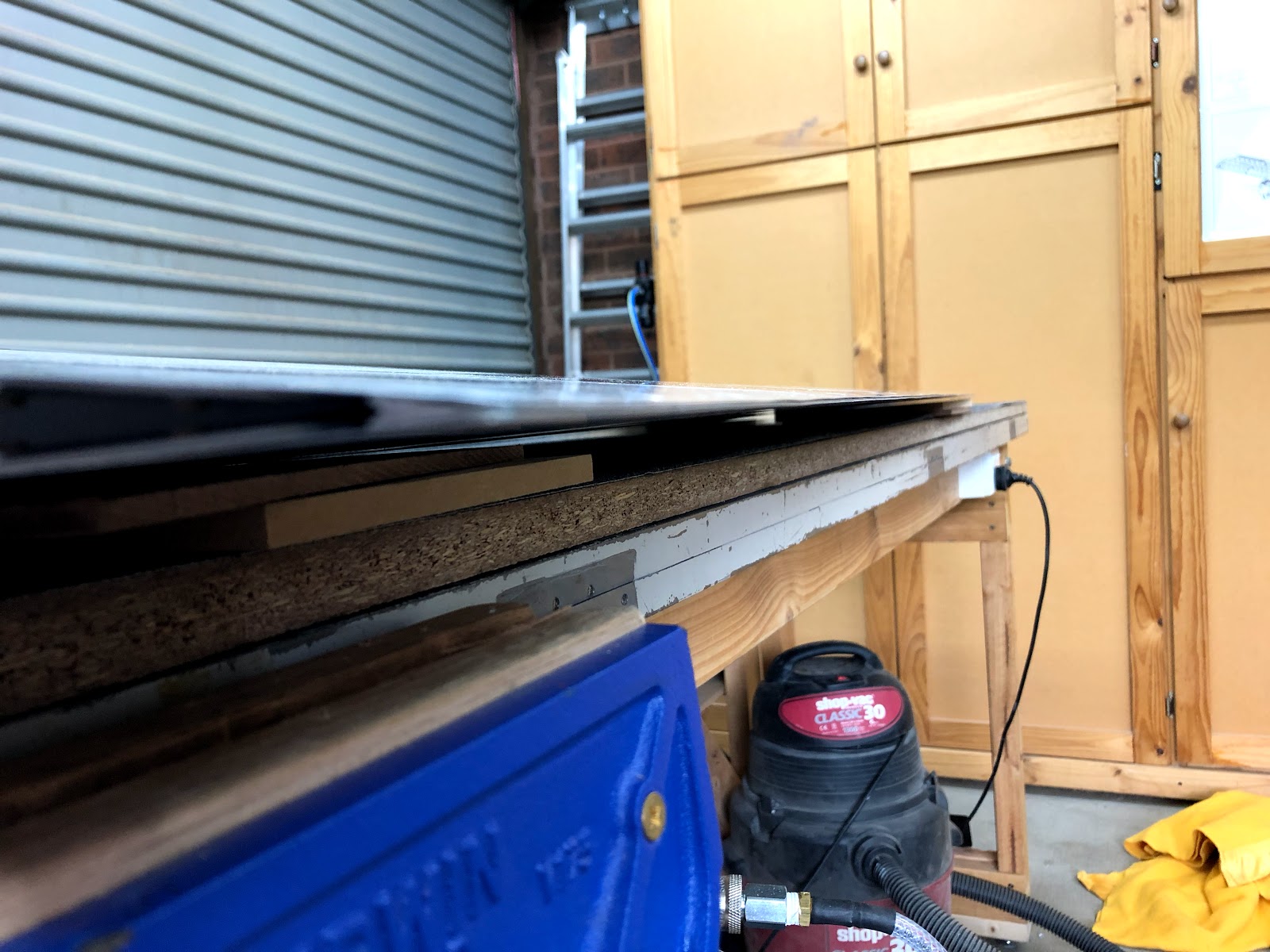
It's hard to get a nice photo of the edge - but when laid on an angle, had slightly less than 1/32" of a bow in the very centre.
When i got the rudder down to Pete's place, i flipped it over on his bench and was completely dismayed to discover that there were some very small 'outie' dints in the skin. It was all i could do but to cry! It seems that when i riveted the rudder stiffners / shear clips together, the hand riveter had banged into the rudder skin and left some dints. I did a test on some 0.016 scrap (same thickness as the rudder skins) and it is remarkably easy to dint this skin. Pete recommended that i lay down some rubber next time: good advice. It turns out that the rivet gun i have is rubbish and really takes a lot of force to snap off the mandrels - meaning the gun really bucks around when the mandrel snaps. So i think i will buy a better quality rivet gun - probably this one.
Pete told me not to dispair however, as i could fix the dints by rubbing them out with the back of a spoon and some grease or vaseline for lubrication. So i got a practice piece of 0.016" and dinted it purposefully with the rivet gun so i could practice getting the dints out. This seemed to work ok, so i moved on the rudder itself. The only word of caution i will give here is DO NOT EVER EVER EVER hit the skin EVEN LIGHTLY with a hammer!!!!.... I was working out the fist dint, and i decided it may go quicker if i just very lightly hit the dint with a soft faced hammer... well this was a BAD IDEA! It resulted in about a 10c piece sized gently 'innie' dint in the skin - much worse than the original dint every was. I was thankfully able to gently massage this out with the back of a spoon from inside the rudder. Overall i was able to work out all the dints in the rudder skin (about 10 of them) and i am now happy.
Below are some photos of the rudder dints after working them out - i don't have any before shots, as they were very hard to get in camera.
7-10: Rudder Skeleton Riveting
Page 7-10 has you insert the rudder skeleton into the skin assembly then begin riveting. It calls for the riveting of the left hand side rudder fairing attach strip aft 8 holes only. You then rivet in the horn brace, and finally finish up riveting the holes common to the skin, bottom rib and attach strip.
There is one rivet that is located aft of the left hand side attach strip, which joins only the R-00904A-1 bottom rib to the left hand skin (with no attach strip). The plans actually never call to rivet this any any stage in the plans i can see, so i went ahead and riveted it at this time. I was able to get in there using the brand new low profile yoke from Cleveland, and by peeling the trailing edge slightly apart.
I made an error here when riveting this attach strip, and actually riveted the whole line of rivets (not just the aft 8 ones). I looked ahead and figured this wouldn't be a problem - but it was (see below).
I then used LP4-3 rivets to attach the 2 bottom ribs together. These went ok, but i found that some of the rivet mandrels were breaking off half way up the mandrel. I am pretty sure this was happening as i was not holding the rivet gun perpendicular to the workpiece (as the thickness of the gun head was interfering). Once i worked this out, and ground the head of the gun down, the rest of the rivet mandrels were ok. I very very carefully used a dremel to cut the mandrels off the rivet heads. I didn't punch the mandrels through, as i believe they are structural in shear for these rivets.
7-10 Step 4 and 5
Moving on, it was time to install the horn brace (and here is where my troubles started!). Because i had mistakenly riveted all the rivets on the attach strip, the forward most rivet interfered with the horn brace and i could not get it installed. No problem, i am good at drilling out rivets... however not in this case! One of the rivets i was able to drill out the head ok, but when i tried to punch it out, it simply would not budge. I think it had expanded between the attach strip and the rib below it. A lesson was learned here - for the aft rivet in any line, you really need to clamp the parts together as there is nothing stopping the end of the part from lifting. An alternative would be to use a bit of small rubber fuel tube to help keep the parts together - must remember to do this!
In any case, i needed to get this rivet out. So i tried using a #41 drill bit to drill the shank out, but did a terrible job of it and elongated the hole!! doh!!! No problem i thought, it was time to get out the oops rivets.
Given the whole point of drilling these out was to get the horn brace in, i then cleco'd the horn brace in and used the LP4-3 rivets to attach it to the bottom rib. At this point, before i riveted the brace in any further, i figured i better get the 2 rivets back into the rudder attach strip / lower rib on each side. And here is were more troubles began!!
I found that there was simply no way to rivet these last rivets successfully with the horn brace in place, as the horn brace did not give enough room for either a bucking bar, not a squeezer set! The oops rivet was so bad that when i shot it, the bucking bar was only half on the rivet - what a mess!!
So catch 22 - i can't seem to get the horn brace in with the last 2 rivets on the attach strips installed, and yet i can't seem to rivet those last 2 rivets with the horn brace installed!! What a pickle.
So what to do?
In the end i really didn't want to use MK319 pull rivets on the lower rivet line if i can avoid it (especially one in the middle of the line!) - so i drilled out the LP4-3 that held the horn brace onto the lower ribs and removed the horn brace. I then riveted the last rivet of the attach strip with a normal AD3 rivet on one side, and an oops rivet on the other side (due to the enlarged hole). This all came out ok. Now, how to get the horn brace in?
It turned out, all i really needed to have done in the very first instance, was to man-handle the horn brace into location. At the end of the day, when i realised my mistake of riveting the whole line of rivets, and had the initial issue of the horn brace not fitting, i drilled out the last 2 rivets in a hurry, with false confidence and not fully thinking it through. This resulted in hours of unnecessary work, and the elongation of a hole needing an oops rivet. If i had have just slowed down and thought things through, i may not have had the issue. Lots of lessons today!
Here you can see the OOPS rivet installed, and the slight paint scratches from man handling the horn brace into position. The silver ring is from where the initial oops rivet was bent over when i tried to rivet it with the horn brace in place. This rivet is set nicely even though the picture looks different. I will just touch these bit up with a brush next time i have a batch of primer mixed.
Riveting the remaining rivets on the horn brace was no issue with the squeezer and the longeron yoke, however i really could not reach the forward most skin / brace rivet on each side, and didn't own a bucking bar that reached into that space. So i decided not to be a hero, and updrilled to #33 and used a MK319-BS rivet here.
MK319-BS rivet installed in the forward most hole. Can always fill these later on.
Step 7-11: Riveting the counterbalance rib, spar and top rib
Next up was page 7-11, riveting the counterbalance rib to the skins. This was done with the swivel head mushroom set and the tungsten bucking bar. This all went well, except in the middle of the rivet line on one side i let the mushroom set wander and bent the very edge of the skin around the curve of the edge of the underlying rib - thankfully no damage to the rib itself. I was able to straighten this with a wide chisel without any issues.
The very small bend on the edge of the skin
Once this was done it was time to relieve the edges of the counterweight where it contacted the rivets. I realised that i had forgotten to prep and prime the R00001 plate which holds the 2 nutplates, so i deburred this, cleaned and just used some white etch primer on it. I forgot to countersink for the nutplates before priming, but did this afterward and installed the nutplates. The counterweight could then be installed in the final position. I used NAS1097 AD3-3.5 rivets on the nutplates instead of the called out AD3-3.5 rivets. These have a smaller head, and you can therefore countersink more easily - i could have countersunk for the AD3 rivets here as the plate was thick enough, but wanted to try out the NAS1097 oops rivets for this application, as there are other places in the kit where i will be doing this. The theory is that a nutplate rivet only needs to be strong in shear (to stop the nutplate rotating), so you can use a smaller head size rivet with no problems.
Counterweight installed - i used the orange stuff more as a test because i had never used it before.
Once the counterweight was in, i then used the squeezer to rivet the line of AD3-3.5 rivets along the spar / skin. I had a lot of trouble with these rivets - they looked ok then i was squeezing them, but when i flipped the rudder over, many of them had been bent over! In the end i had to drill out around 40 rivets out of the 100 on the two sides. Pete mentioned that a lot of the time, when this is occuring it is due to the river being too long. So i placed a -3.5 rivet into a hole and used my gauge - the rivet was very slightly longer than needed. I then put a -3 rivet into the hole, and it was very slightly shorter. So i ended up using the AD3-3 rivets in the 40 locations, and these squeezed much better.
Next up i riveted the top rib into place using the squeezer - and also finished the final rivets where the 2 skins overlap. MK319-BS rivets were used in the last 3 holes on each side of the top rib, as the gap is just too small to fit a bar in.
MK319-BS rivets used in the last 3 holes.
I also had a helper in the shop today:
This left the rudder mostly finished - next up i will need to rivet the trailing edge, and roll the leading edges: