Search Build Log

Showing posts with label 25 - Fuse Bulkheads. Show all posts

8 Dec 2022

25-03 -> 05: Completing Aileron Bearing bracket / Cover Ribs / Bulkheads

As previously mentioned, i had an issue with the alignment of the bearing bracket parts. These were double flush riveted together, then once this was done i was able to continue with the steps on Page 25-03. 

This involved riveting these brackets to their respective cover ribs, then installing the ribs on the forward mid-fuselage bulkhead. The bearing bracket cover ribs were installed with bolts and torqued to spec. They were then riveted using the long straight set, as per all the other cover ribs. 

Bearing bracket cover ribs bolted in place.

Once these were installed, i clecod on the bearing brace to each cover rib and spar. The 8/32 structural screws were installed with nyloc nuts. These were difficult to install - i had to use my 90 degree ratchet screwdriver and i didn't have a spanner which fit an 8/32 nyloc nut! (so used my knipex parallel pliers). 

These were then riveted to the spar using the long straight set. To rivet them to the cover ribs, the rivet closest to the spar could only **just** be reached using the pneumatic squeezer. 
On this angle, the squeezer would not fit.


But by standing it up there was **just** enough room to get it to fit.


Reaming Time

The last task of Chapter 25 was to ream the bolt holes in both bulkheads. This was actually a very easy task, as the thick spar bars were already to the correct size and the reaming was to just shave a tiny bit off the side angle, or rib on the other side of the bulkhead. I just did it slowly using the hand drill. 


...and that concludes Chapter 25! 


25 Nov 2022

25-04 -> 05: Mid Fuse Forward Bulkhead / Cover Ribs

I started our by deburring all the required parts for this section, including the side angles, cover ribs and bearing bracket support ribs. The bearing brackets themselves were covered in a previous post.

The bearing bracket supports were 'suicide countersunk' as i could not use a countersinking cage here. 

I was then able to prepare all the cover ribs including dimpling along the bottom, and installing nutplates. Page 25-04 was very complicated with regards to what cover ribs were dimpled on the top, and which nutplates went where, but after going slow and reading it 50 times i think i got it right! 
All the cover ribs have the same holes - but some are ignored.

These are the bearing bracket rib support brackets. 

I then moved onto countersinking the mid fuse bulkhead forward spar flanges - for the dimples in the skin along the bottom flange, and for nutplates along the top. I had some paint left over from spraying the cover ribs the day prior, and was able to cover it and keep it in the fridge, so could prime the countersinks on the spar flanges. Nutplates were installed along the top flange. 


I was now ready to begin riveting things to this spar - i started with the side angles. These are bolted and then riveted. These were riveted on using the gun and bar with the assembly standing up and clamped to the table. 


I was then able to stand the assembly up and using shims clamp to the bench. I clecod on the cover ribs and bolted and torqued each bolt to 38 in/lbs (28 in/lbs plus some running torque). I then riveted on the cover ribs - i was able to use the long straight cupped set for most of these, set at 55psi. For the topmost rivet, the straight set did not fit due to the top flange of the cover ribs - so i had to use the double offset set. 
The long straight set is a great tool. 


The long straight set did not fit.

Here you can see all ribs riveted, but the bearing bracket ribs are not ready to be installed as yet.


Of course, torque seal used on all nuts as soon as the torque is set.

At the completion of this section, i had not received the new bearing brackets as yet, so the riveting of the bearing brackets ribs and support brackets will occur once the new bearing brackets are done. 

I will add the pics of this when it is completed. For now, section 25 is complete pending the arrival of the additional parts, so i will move onto section 26 - Lower Mid Fuselage.


25-03: Bearing Bracket Misalignment Issue

Page 25-03 has you prepare the bearing bracket parts F-01450-L & R into pairs. They are identical when you receive them, however you have to countersink them on the outboard sides such that you end up with a couple of pairs of the brackets, matched to each other. They then have a COM-3-5 bearing installed and they are double flush riveted together before being installed on the Cover Ribs, which are then installed onto the forward centre bulkhead using bolts and rivets.


So, all was going well. I managed to get all the countersinks in the correct locations on the correct side of the parts. The parts were clecod together and the edges filed and deburred so they match together as a couple of pairs of parts. 

I then cleco'd the parts together with the bearing in place. One pair of parts went together fine, however the other one was very misaligned; to the point where i was unable to get a rivet into the holes. I believe that when the parts are manufactured, they machine out the bearing recesses into a large sheet of many bearing bracket parts. Then then take the sheet to the punch and stamp out the brackets themselves with all the rivet holes. I imagine there is a very large sheet of many brackets done at once. I think that perhaps, in the drawing, one bearing recess is drawn slightly out of kilter in relation to the holes. Other people have reported they have no problems with these parts at all - and one pair of my brackets is fine. 

Here you can see how the once perfectly aligned edges are no longer aligned once the bearing is put in place.


With no bearing in place, the edges are aligned perfectly

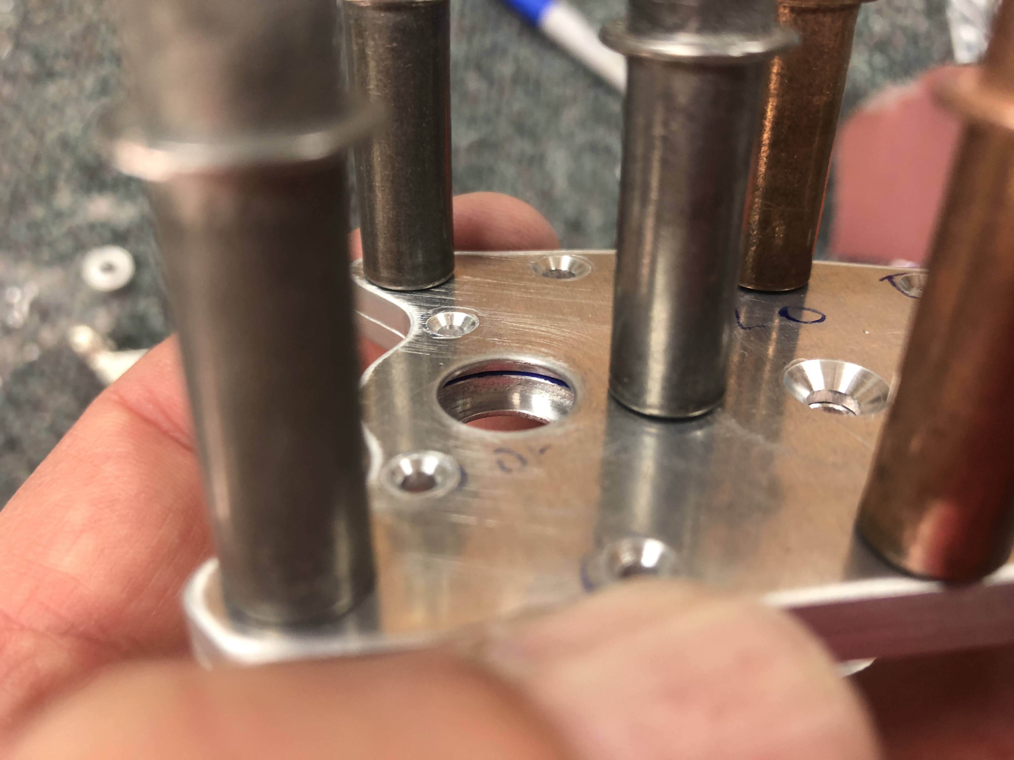
Here you can just see a sliver of blue inside the bearing recess hole. I drew some sharpie on one part and the blue shows that when the holes are lined up, the bearing recesses on one side of the parts doesn't match the other side. One side has been machined out of kilter in relation to the rivet holes.


This shows how far out of kilter the rivet holes get when the bearing is in place. I was not able to get a rivet in these holes, and if i reamed them out the other side would have been significantly oval.

With the screws in place, and the bearing installed, the rivet holes are all out of alignment. 

In any case, i sent and email to Van's about the problem, and posted about the problem on the RV-14 Forum on Van's Airforce. 

Support came back and offered to replace the parts. So i put this section on hold and moved onto Section 26. A month later... the new parts arrived. 

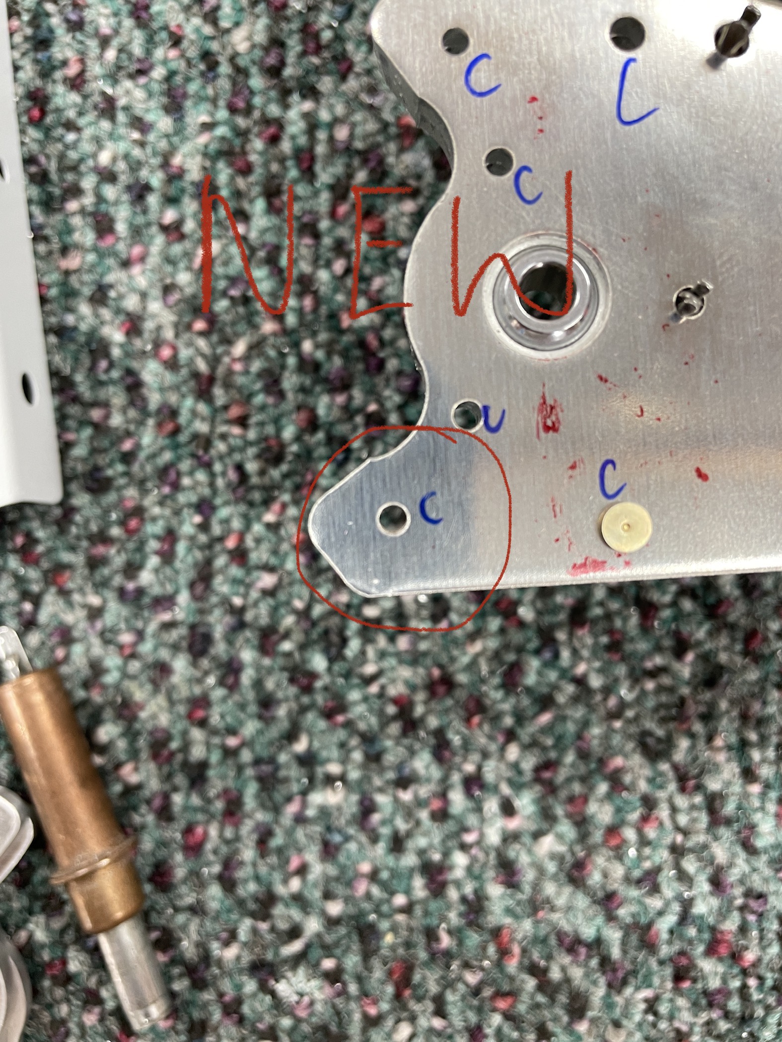
The new parts arrived and i immediately went out to the shed to see if they had the same issue:


As you can see, the new parts had no misalignment, which supports my theory that at least one bearing recess drawn in the set of parts is out of whack, while the rest of the parts are ok. 

So i moved on with the section, and countersunk the new parts, deburred and filed the edges to match as a new pair and then primed them. 


Once these were dry, i was able to double flush rivet them together using the squeezer and finally rivet them to their cover ribs. The bearings on both are free and loose. 

I double flush riveted these together with the screws in position. The plans call for -7 length rivets, but as per the wiki, these are too long. -6 length worked perfectly. 

-7 rivets would have been too long here. 


26 Oct 2022

25-02 -> 03: Fuselage Centre Bulkheads - Mid and Aft

Starting on the fuselage kit in earnest, i am glad to see that there is a good mix of parts prep and actual building. The wings felt like i was deburring for an age, then priming for an age, then riveting for an age. This kit seems to mix it up a bit! 

Aft Bulkhead - Parts prep

The aft bulkhead is the one which has the seat backs resting against it. It also contains the 'bulkhead attach bars' which attach to the rear spar of the wing. Work started by deburring these as two pairs. I also deburred the lower and side channel, and associated doublers for this bulkhead.

I used the "WHANG!" technique here again.


Marker helped to see when i had filed them to match


This shows the aft bulkhead arrangement

Mid Bulkhead - Parts Prep

The mid bulkhead consists of a large spar section made up by vans and anodized an appealing orange colour. There are 2 side channels which needed to be deburred. The spar flanges needed to be countersunk for the lower skin rivets, and on the top side, for nutplates. I put a little spot of primer in each countersunk hole. 


Nutplate attach rivets were countersunk flush..

...whereas, skin rivets were countersunk 0.007" (7 clicks) deeper than flush.


A Small Holiday

I took a few days off and borrowed a mates bonanza to go and visit Narromine, NSW for AusFly - the Sport Aircraft Association Australia (very!) mini version of Oshkosh... 


Making Bulkheads

After our little holiday, and motivated to keep building, i primed all the mid and aft bulkhead components and started assembly. 

Assembly started with riveting some doublers to the lower and side channels. These are located where the bolts for the wing attach bars are located. The plans call for riveting the holes common to the doublers, side channels and bottom channels. However, there are 2 rows of rivets on the top of the outboard doublers which are common only to the side channels and the doublers (not the lower channel as well). I looked way ahead in the plans but could see no reason why these shouldn't be riveted now. I also asked a question in the RV14 forum to make sure i wasn't missing anything in riveting these now. Also, the plans state to place the manufactured head of the doubler rivets aft - but the top two rows will be seen from the cockpit, so i elected to put the manufactured heads forward (the rivets in the floor panels in front of these rivets are pull rivets, so should be fine). 

I managed to set all these rivets using the squeezer and the longeron yoke. For the most inboard rivets, the only way to get the longeron yoke in place was to remove the cupped rivet set, slip the yoke over the flanges, then put the cupped set back in place to set the rivet. 

The small, inboard doubler.


These are the 2 rows of rivets visible from the cockpit.


Attach Bars - Riveting and Reaming.

Next up i needed to double flush rivet the attach bars together. The plans ask you to bolt these to the rear spar using a 3/8 bolt - which i didn't have because i live in a metric country! Off to the shops to get a 3/8 bolt, as well as some 5/16-24 (5/16 UNF) plain nuts and washers to attach the bars. The bars were bolted to the rear spar and i used a -6 length AN426 rivet - but this was way too long. I then cut down a longer rivet to -5.5 but this was also too long. For anyone following, a -5 length rivet is perfect here. 


-6 length on the left, and a -5.5 on the right. Both too long. 

-6 on the left, and -5.5 on the right. I could not get the squeezer to set these flush.

So out they came!


Once i had the bars riveted together, i was able to follow the detailed process for reaming the bars to the bulkhead. I did not use a drill press, but was just very careful and used a square next to each hole to ensure i reamed the holes normal to the surface. The bolts were installed with Tefgel, and i put a little bit of LPS-2 on the bars to try and stop the primer sticking to itself between the bars and the bulkhead. As per the plans, the bars were installed with temporary nuts.


The forward bulkhead side channels were riveted to the forward bulkhead spar using a rivet gun and bar. When riveting, i realised i had countersunk the 2 flush rivet holes on the right side channel in the wrong spot. I ended up countersinking the correct hole, and then installed a flush rivet in the hole which should have had a normal one. (I don't think this really matters - should be a similar strength). 


You can see the bottom 2 centre holes should have been countersunk. 


Got it out with no issues

and countersunk the correct holes

and now have an extra countersunk rivet on one side. Don't think it should matter tho. 


This completed the mid centre and aft fuselage bulkheads.