Search Build Log

Showing posts with label Workshop. Show all posts

3 May 2024

Fuel Line Straightening Tool

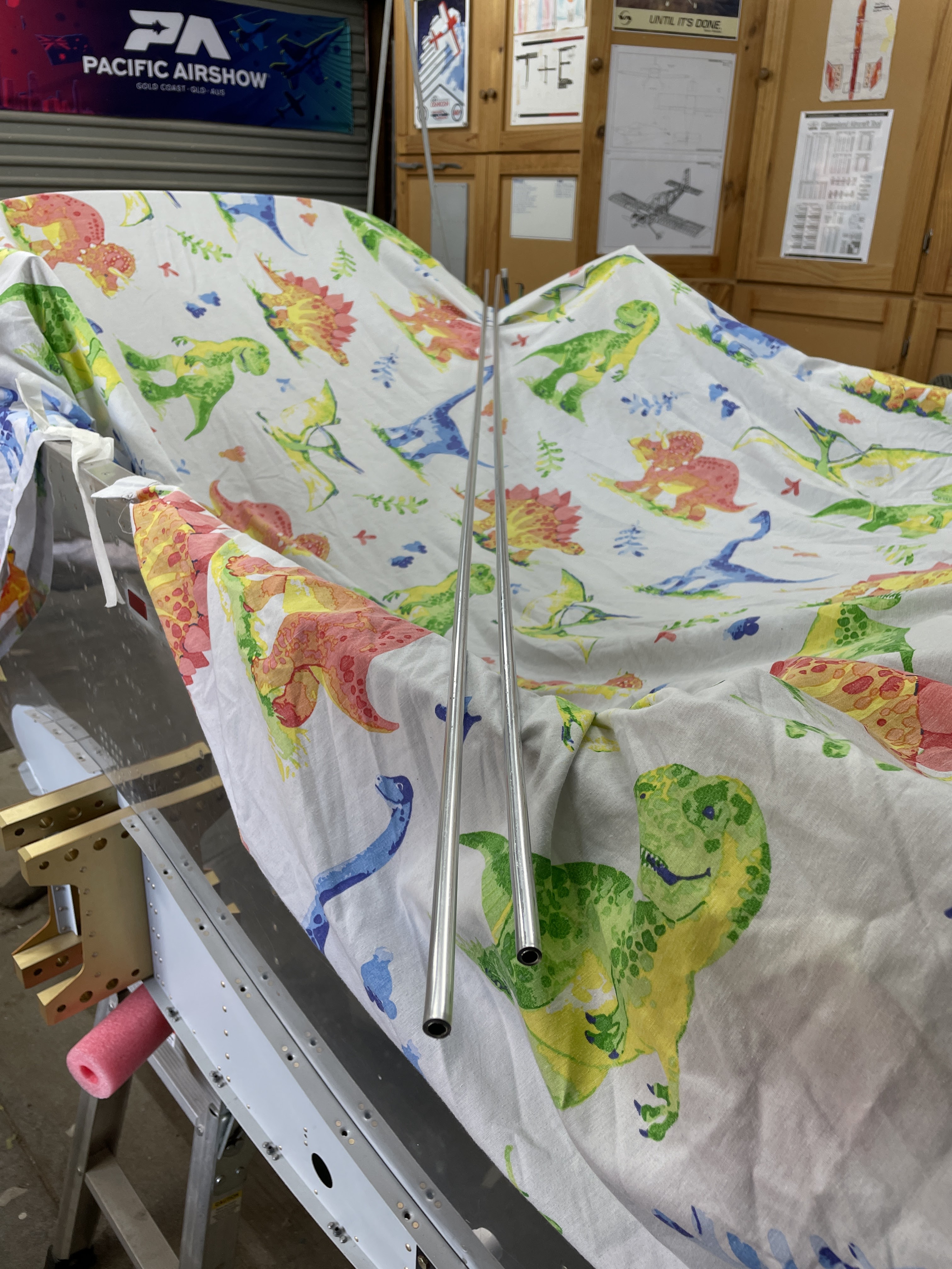
The Fuselage kit came with a 9ft roll of 3/8" 3003 Aluminium Tube for manufacturing the fuel lines. The trouble is that the soft line comes as a coil and needs to be straightened before use, if you want a decent looking set of fuel lines. 

I initially straightened them somewhat by unrolling on the concrete floor. But to get them truly straight, i went to the local Hammerbarn and purchased some concave rollers, designed for roller screen doors. These were screwed onto some left over bits of plywood, and a couple of M6 bolts and wingnuts were used for tightening. This tool gets run back and forth on the tube and does a very good job of straightening it. 

If the tube still has a little wave in it, i clamped one end into the vice and clamped on some vice grips to the other end, and gave it a couple of whacks with the hammer. 

The end result was a couple of lengths of straight tube, ready to be sacrificed on the alter of learning how to bend fuel lines! 


This was the tube after rolling out across the floor

and after using the roller tool

I bet most of this will end up in the bin!


8 Sept 2023

Building a Fuselage Rotisserie

Since it has taken me 45 mins to set 8 rivets on the seatbelt lugs, and since i had to climb in and out a hundred times, i realised there needed to be a smarter approach to riveting the tailcone to the fuselage. 

I had previously purchased a SuperCheap Auto Engine stand when they were on sale, so now was the time to convert this into a rotisserie. 

There were a number of plans online for this, and many builders who had gone before me. I had initially planned on using timber to make the frame to attach the firewall to the engine stand, but in the end went with 50mm square galvanised steel tube. 

The lower piece spans across the bottom engine mount bolt locations, and there are 2 radial arms which reach to the top bolts. I templated the bolt hole locations using brown paper, including the shape of the firewall edges. The steel was then bolted to the firewall with some washers to ensure it did not contact the firewall at all. The tail of the aeroplane just sits on a padded saw horse. 

This design allows me up to 90 degrees of rotation in either direction, which proved very valuable for gaining access for riveting of the tailcone to the fuselage. 

The stock engine stand is angled backward which would have lifted the tail of the fuselage high into the air - so it was modified to remove this angle. 


The base was bolted together and i came up with a plan on how to lift the fuselage into the stand.

Brown paper was used to template the distance between the 2 lower engine mount bolt holes, as well as outline the shape of the side skins at each end (to trim the steel tube so it cleared the cowl attach hinges).


These holes were then transferred to the steel tube, and the tube was drilled and trimmed.

The engine stand plate was then centred on the lower steel tube, and drilled for the large bolts which came with the stand. 


I then bolted the assembly to the lower engine mount holes. 

Brown paper was again used to template the hole location as well as the shape of the sides for trimming later. The length of the tube at the engine stand end was not critical so was not templated.

One shorter tube per side was marked to the template, and drilled and trimmed

The radial tubes were then bolted to the firewall, aligned with the holes in the engine stand, marked, removed and drilled for the large bolts attaching the tube to the engine stand plate. 

The finished product. Note the cardboard - i actually added some washers to the engine mount points to move the assembly slightly away from the firewall to prevent the mount bolts contacting and damaging the firewall. 


Torque seal was added to these bolts (just in case). 


When not being rotated, or when climbing in, the fuselage is supported underneath.

So far the rotisserie has worked out great - for the next steps it was invaluable in riveting the tailcone to the fuselage. 

5 Aug 2023

30-02: Baggage Bulkhead & Workshop Preparation for the BIG JOIN!

Chapter 30 stated by preparing the baggage bulkhead parts. These will need to be primed and ready to go for the big event - the tailcone to fuselage join! 

Seatbelt lugs chamfered on the edges, and countersunk for the dimples in the skin.

Evidence of Part Prep

The baggage bulkheads and seatbelt lugs.


Workshop Updates

When we moved into this house, one of the criteria was a shed big enough to build an aeroplane. This house had a large shed, however the last owner had build a wall half way along and lined and carpeted the back end. The first thing i did was put in a sliding door between the 2 rooms, and i had done all of the empennage and wing construction in the back room. Which meant the wings, tailcone and empennage were entombed in the back room with no way to get them out! 

I was time to rectify this unacceptable situation, by cutting a big hole in the wall! 

Before!

No way the tail would fit through that door!

But will fit through this hole - no problems!


27 May 2021

17-08: Riveting Leading Edges to Wing

Wing Cradle Modification

In order to hold the wing in the wing cradle once the leading edges were installed, i had to modify the cradle with a sling arrangement such that the wing would be safely held with the leading edges in place. 

The wings were removed from the cradle - one put on saw horses temporarily, and the other placed on the bench. The one on the bench was placed so i could cleco on the leading edge for riveting. I used shot bags to make sure it didn't fall off the bench, but most of the weight is aft of the spar anyway.


The wooden "cross bars" that were at the outboard end of the cradle were removed, and i installed some metal shelf brackets to help brace the vertical 'legs' of the cradle, and stop them leaning inward with the weight of the wing. This was probably overkill, but i had the brackets in the cupboard so i figured it wouldn't hurt.


I used some solid 3/4" plywood to make 9 'clamps'. 


I purchased some 'seat belt' type strapping which was good for 2,200 kgs - should just be enough :) 


I measured the leading edges, and cut & clamped the strap so that once the wing was placed in the cradle with the leading edges installed, the spar would be relatively level, and i would have access to set the leading edge skin to spar rivets.


Riveting on the Leading Edges

The first leading edge was clecod on, and the the fit against the top skin was checked. I made sure there was about a 1/32"-ish gap the whole way along the leading edge skin - basically so i could just see a sliver of green primer on the spar flanges through the gap. These will be filled with paint eventually, i think. I also made sure that the tie down rings screwed in without interfering with the skins.
I had to lay on the ground with a torch, to check the fit of the leading edge skin against the top wing skin.

All ribs except the most onboard one was installed with pull-rivets (of a couple of different lengths). I made sure to use a piece of cardboard on the skins in case the rivet puller bumped into the skin when the tail snapped off (as happened on the rudder skins). I used a small piece of rudder trailing edge as a wedge to allow the rivet puller to fit (where this was necessary). 

Here you can see the little wedge in action

This makes me happy


The inboard most rib was installed with AN470 rivets - i used the offset rivet set on these at quite a high pressure of 60 psi. 


Bucking bar bruises

Once the ribs were riveted to the spar, the wing was placed in the cradle. I was able to use the squeezer to set all the flush rivets along the bottom flange of the spar, but was not able to reach the top skin rivets by myself. My mate Kingers helped me on this one - i ran the gun and he was on the bar. We used a couple pieces of thin ply as a shim to make sure the bar stayed normal to the spar flange and all these rivets went without having to drill one out.
The setup on the cradle was perfect - very easy access to the top skin rivets. For the second wing, we just swapped the wings over and put one wing back on the workbench. It will stay there anyway, in preparation to install the fuel tanks.


Access using the squeezer to the bottom flange of the spar was easy using this arrangement. I am very happy with this cradle - it has worked out great.


Right Wing - CLECO Free since 2021!

Next up is the landing light lenses, priming the outside of the fuel tanks and then installing them on the wing.