Search Build Log

Showing posts with label 28 - Lwr Fwd Fuse. Show all posts

27 Mar 2023

28-09 -> 10: Battery Box and Heater Vent Boxes

As always, the first step is drilling and/or countersinking. In this case, it was the battery box. This is held together at the bottom with flush rivets, and is also riveted to the firewall with flush rivets. I had to be quite creative with the countersinking! 

The suicide countersinking tool! I went slowly and constantly checked i was not going to deep.

I tried to use the 90 degree bit on the lower holes behind the front lip of the battery box, but could not get in straight. 

Probably should have deburred the part before countersinking!

Ended up flexing the lower lip of the box to reach the lower holes using the long drill extension.


The battery and heater vent boxes were primed along with the remaining parts in Chapter 28, and then all aluminium parts which will be in the engine compartment, were top coated with black high temperature engine enamel. I riveted the battery box together before applying the black engine enamel. 

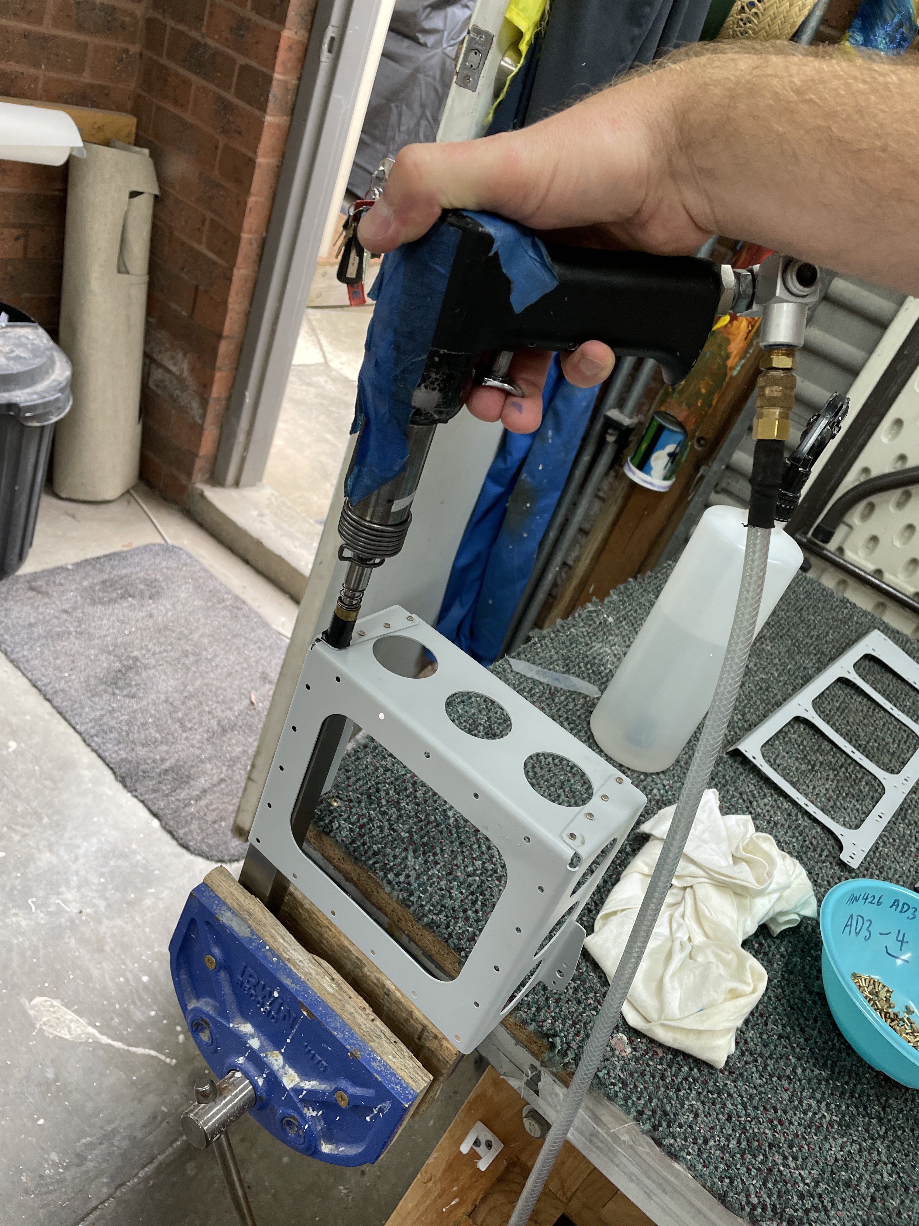
I could use the squeezer on the forward 3 rivets, but could not get the squeezer onto the back most rivet. 


To reach the back most rivet, i placed my long "special elevator bucking bar" into the vice, and backriveted the corner rivet.


To make up the vent doors, the first step is to fabricate a hinge from some stainless hinge material. The kit provided a 6" long piece of material for this purpose - I was able to cut it up using the metal Dremel wheel - the bandsaw wouldn't touch it! 

One interesting point - is the plans ask you to make it up out of "MS20257-C2 Stainless Hinge raw material". However, the kit comes with a part labelled "7200x6" - this is the stuff to use. 

Once the parts were deburred, i cut the hinge pin ever so slightly shorter than the length of the hinge, and closed the eyelets at the both ends a tiny amount - just enough to stop the pin falling out. 


Squashing the end eyelets ever so slightly.

The hinge door comes with an extra piece at the bottom edge, which is used to align the hinges for match drilling. I did so using some boelube and the drill at a slower than normal speed. Once drilled, the lower 'extra bit' it cut off (save this piece - don't throw it away!).  Everything was deburred and dimpled and the hinge is attached to the vent door using stainless steel rivets - they were a real pain to set using the squeezer. I recommend backriveting these for anyone else following. Mine bent over every so slightly - but i decided not to try and drill them out given how hard they are. 


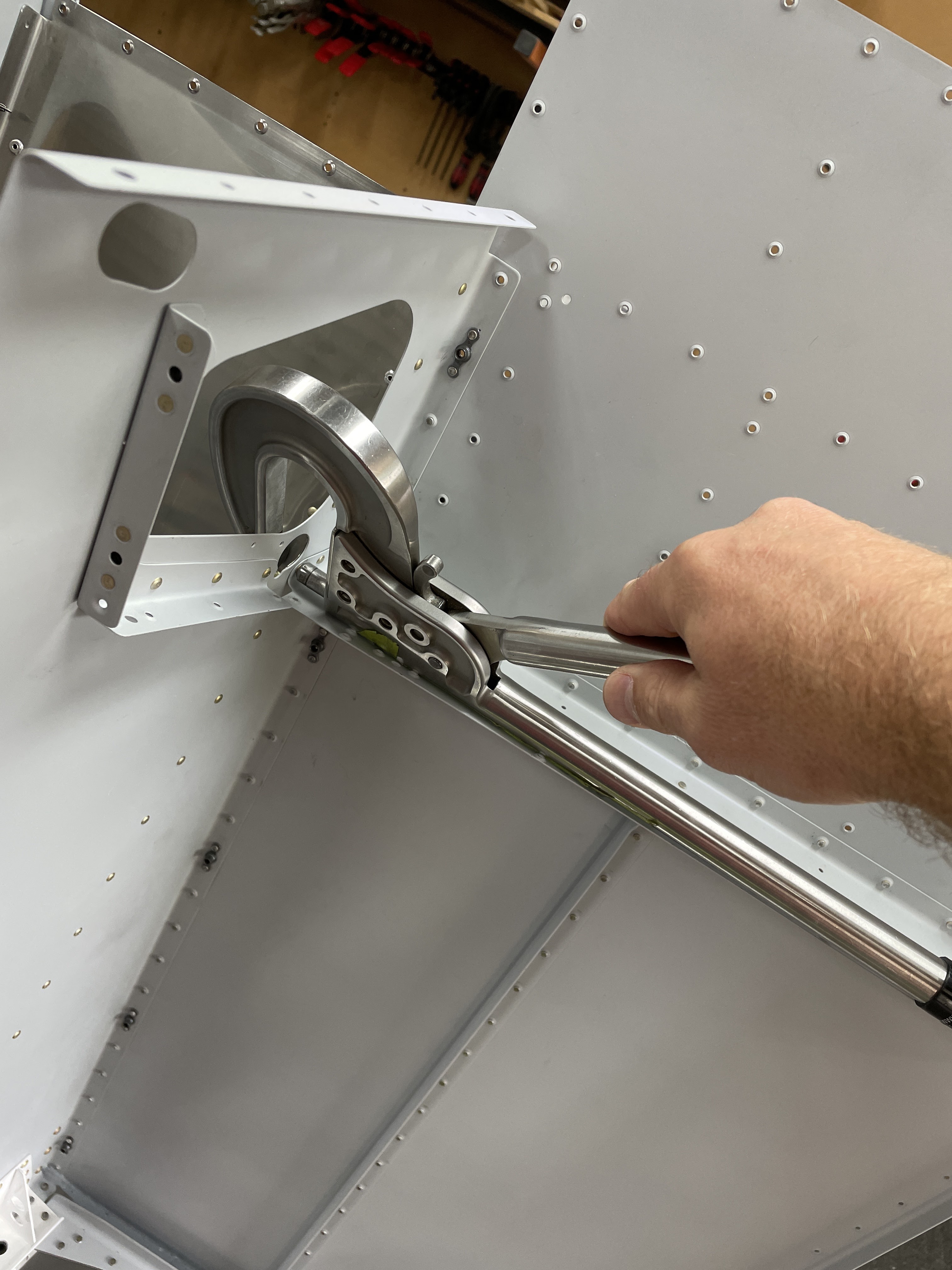
Now, if you cleco on the hinge doors to the firewall, you will notice that the lower hinge attaches straight to the surface of the firewall. But he upper hinge, has the vent door between the hinge and the firewall surface - this makes it impossible for the vent doors to sit flat against the firewall! The undocumented solution is to use the little piece of stainless you cut off the vent doors as a shim under the lower hinge (between the lower hinge and the firewall). The following video illustrates the issue and solution:

Once the vent doors are made up, the vent arms are riveted on, also using the painful stainless rivets. The vent door assemblies are then riveted to the firewall using AN470AD3 rivets on the lower hinge. Given how thin and flexible the firewall is, i placed the manufactured head of all rivets for the vent boxes on the inside, against the firewall sheet (and set the shop heads on the forward side). 

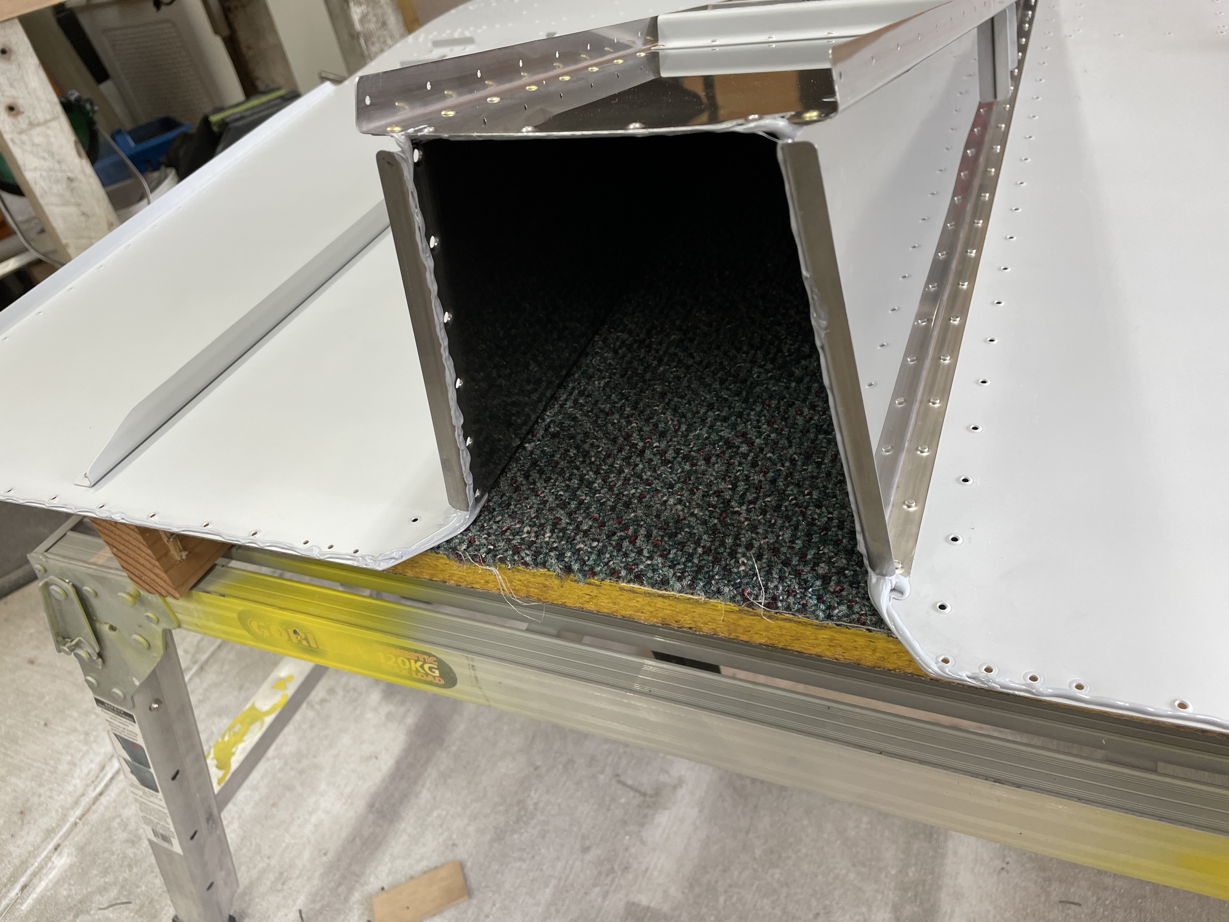
Once the doors are in position, i was able to rivet the vent boxes together. On Page 28-09 the plans ask you to rivet the vent door sides to the vent inlets using 4 x LP4-3 rivets. 

However, if you read forward in the manual to the Firewall Forward chapter, Page 48-02 (or on the OP62 - EXP119 KAI, Page 62-17) it asks you to modify the right vent box, by drilling out 2 of the 4 LP4-3 rivets on the right hand side and riveting on a blanking plate. 

Hence, i decided to rivet the left heater box assembly together using all 4 rivets, but rivet the right one using only the top 2 rivets. These were then riveted to the firewall, keeping the manufactured head on the aft side (as the firewall sheet itself was the most fragile). 

Right side box was assembled using only the top most LP4-3 rivets.

The aft side components - the hater cable mounts to the vertical arm and actuates the door using the arm riveted to the door. 

Finally, with my Dad's help we back riveted the battery box to the firewall. Dad held the bucking bar on the forward side (inside the battery box) and i set the rivets from the aft side. The only exception was the 2 rivets right under the firewall cross member - why Van's didn't just move them down 1/4" i will never know! For these ones we had to use the backrivet set on the front side (on the flush manufactured head) and i used the angled end of my tungsten bucking bar on the shop head. 


The top 2 rivets right under the cross member were a pain - i used a bit of cardboard on the cross member to protect the paint, and use the angled bit of the tungsten bucking bar to set these rivets.

This completed Chapter 28! 

28-08 & 11: Attaching Forward Centre Bulkhead Assembly / Cover Panels

It was finally time to attach the Mid Fuselage Forward Bulkhead (and Cover Ribs) to the lower forward skin and firewall assembly. It us nice to go into the back part of the shed and pickup a large component to rivet to another large component - major visual progress! 

First up was to prime all the remaining components in Chapter 28, including the cover panels and the battery box and heater box parts. 


Work started by riveting a few small components - the fuel selector plate, and the 'wire routing channel' in-between the 2 tunnel sides. I was then able to get the forward bulkhead assembly and cleco into position. I riveted the web of the cover base to the flanges of the cover ribs using a hand squeezer. 

Major Visual Progress (MVP)

Web of the cover base to the flanges of the cover ribs was done with a hand squeezer.

I was then able to stand the whole assembly up, with the firewall down to rivet the cover ribs to the lower skins. Due to the flanges of the firewall, and the lower cowl attach plate protruding forward of the firewall skin, i used a couple of pool noodles to space the firewall off the 'bench'. Riveting the cover ribs was a fairly easy task - however - i dropped the bloody bucking bar onto the firewall!!! I should have known better and placed some padding down on the firewall. Anyway, the general consensus is that I am going to do way more damage trying to get this little 'outie' to push back in, than just leaving it alone. So alone it will be left. (Insert Adult Language Here). 

This position gave me really easy access to the rivets between the cover ribs and the lower skins.

These rivets were set using the swivel mushroom set on the skin (set to 25 PSI) and the small tungsten bucking bar on the inside (which is unfortunately, subject to the laws of gravity).

A pool noodle kept and assembly up so it didn't crush the lower cowl attach plates and firewall flanges.

Lightly clamped for stability.

This is what i SHOULD HAVE DONE!

The dent!

I know where it is!


The last step is to bolt the tunnel sides to the forward centre section bulkhead - this was a fairly straight forward task using the gun and bar, however the manufactured heads of the rivets had to be on the spar - there was no way to get the gun into the tight space to put the manufactured head of the rivet on the thinner tunnel side flange material (as is normal shop practice). 

Shop heads on the thinner flange of the tunnel sides - no way to fit a gun in here.


Riveting the Cover Panels on the Cover Ribs

Skipping ahead to Page 28-11, it was time to rivet on the cover panels and their respective nutplates to the cover ribs. These were all done with the pneumatic squeezer, except the 3 rivets which are on the most inboard ends of the cover panels, right against the tunnel sides. For these, i had to backrivet them - a fairly sketchy proposition! I damaged the primer here from the backrivet set, and it will need touching up next time i have some paint left over. A note in the RV14 Wiki plans reminded me that the top flange of the cover panel goes UNDER the top flange of the cover ribs - the image on Page 28-11 is misleading.


Next up is to finalise the last few things on the firewall, then Chapter 28 is done!

20 Mar 2023

28-05 -> 07: Attaching bottom skins to firewall assembly

Next up was to attach the bottom skins to the previously completed firewall assembly, including using Firebarrier 2000+ on all the joints. The parts were joined together with clecos, and the sealant was left to cure before the riveting took place. 

Sealant applied along any edges where gas could travel from the firewall into the cabin.


The plans call out pull rivets on the sides of the curled flanges, but solid rivets on the top. I ended up using pulled rivets on the top as well - as i was on my own and could not rivet these by myself.

Made sure to seal all the gaps up.


The transition between the side and top curled flanges was a good leak point, so liberal sealant was used. I also covered the tails of the pulled rivets in case they leaked.

I placed a fillet along the inside corner as some extra insurance.


Next up, i riveted the cover bases to the lower skins and the skin stiffner. I stood the assembly up, placed rivets in all the holes and covered them with backrivet tape. I then laid the assembly down and back riveted these. I also riveted on the cowl attach bar, but realised it went over the bottom skins and that i had not primed in this area. So cleaned, scuffed and primed the skins where the bar will go. 


Cover bases were backriveted to the bottom skins,


Like an operating theatre!


Bottom bar installed with primer in between the parts.


OP62 - EXP119 Engine MOD

OP62 is the plans document which covers the installation of the EXP119 engine from Lycoming, and there are a couple of changes the plans request for Chapter 28. The first was the modification of the lower cowl attach plates. Being unsure at this stage if i will install this engine, i elected not to cut down these plates and riveted them on at their original size. I can always trim them later on with a Dremel.

The plates were primed with zinc chromate primer, then painted with the same black engine enamel as the exhaust hangers, for increased resistance to fuel and oils. 

Nutplates were added later - i had to order more, as i used them on the tunnel sides (below) and ran out.


The other change in Chapter 28, is the addition of some nutplates. These are added to the line of rivets which attach tunnel sides to the lower skins. I elected to complete these at this time, as if i decided to do it later it would be much more difficult. If i decide not to use the EXP-119 engine, i can just screw some pan head screws into these holes.

These were attached along with the tunnel side to bottom skin rivets. The plans call out -3.5 rivets, however these were too short. I set a whole line of them but didn't like the heads, so drilled them out and replaced them with -4 rivets. I used -4.5 rivets on the nutplates attach holes. 

To add the nutplates, i used a nutplate of the correct size, screwed a -8 screw into it, and cut off the head of the screw with the dremel. I then used this as a nutplate jig to drill the nutplate attach holes.

The only issue with this plan was that i had dimpled the holes in this area. I would recommend anyone wanting to do this step, to plan ahead and not dimple the tunnel sides, nor the bottom skin at the nutplate locations called out in the OP62 plans. As it turned out, drilling to the screw hole size removed 95% of each dimple - i filed the rest down a little so the nutplates would sit flat. 


I used the rubber tube trick to make sure the nutplate ears sat down flush.

This is what the rivet looks like after a couple of hit to set the rivet. The tube is then removed, and the rivet set completed.

The completed nutplate. 

The most forward nutplate pictured, needed to be installed using a gun and the bar, as i could not backrivet this like the rest (due to the weldment pictured). 

Tunnel sides riveted including OP62 nutplates - do not dimple these holes in the tunnel sides and the bottom skin if you are going to install these nutplates.

Tunnel Sides

Next, i completed the riveting of the tunnel sides to the stainless exhaust ramp. I initially tried to use the squeezer on these rivets, but due to the angles involved it just was not giving a good result. The yoke was dragging on the muffler ramp and marking it up. In the end i used a gun on the rivets and a bar on the muffler ramp size. Had to use the weird footed bar on the forward most rivet. For the aft most rivet (the one common to the cover bases) - the hand squeezer just fit. 


Firewall Penetrations

The firewall penetrations were deburred and cleaned, then installed using Firebarrier 2000+


Turns out i don't have an 11/32 spanner for these nuts! (but did have a socket).