The process of checking the elevator stops was a bit confusing, there are elevator deck stops, as well as control stick stops. At the beginning i didn't fully understand what the purpose of each was, but in essence it is simple: The aft decks stops are there to control the deflection of the elevator - after which, if you kept pulling on the stick you can over-stress the control system. The stick stops are there to prevent this overstress.
As such - the elevator system must hit the aft deck stops, just before they hit the control stick stops.
To achieve this, the plans have you check the forward and aft deflections of the stick bases versus the seat angles. This is to make sure that you have enough range in the stick stops, to achieve the required actual elevator deflection. You also make sure that both sides hit the stick stops at the same time - i only needed to file the lower left side a little bit to ensure they hit at the same time.
Next up, to check the deflections of the elevators, i needed to install the horizontal stab and elevators. This meant a large re-organisation of the shed - i was luckily able to fit the installed HS between the spray booth and the opposite wall of the shed with about 2cm on each side.
 |
| Haven't seen these in a while! |
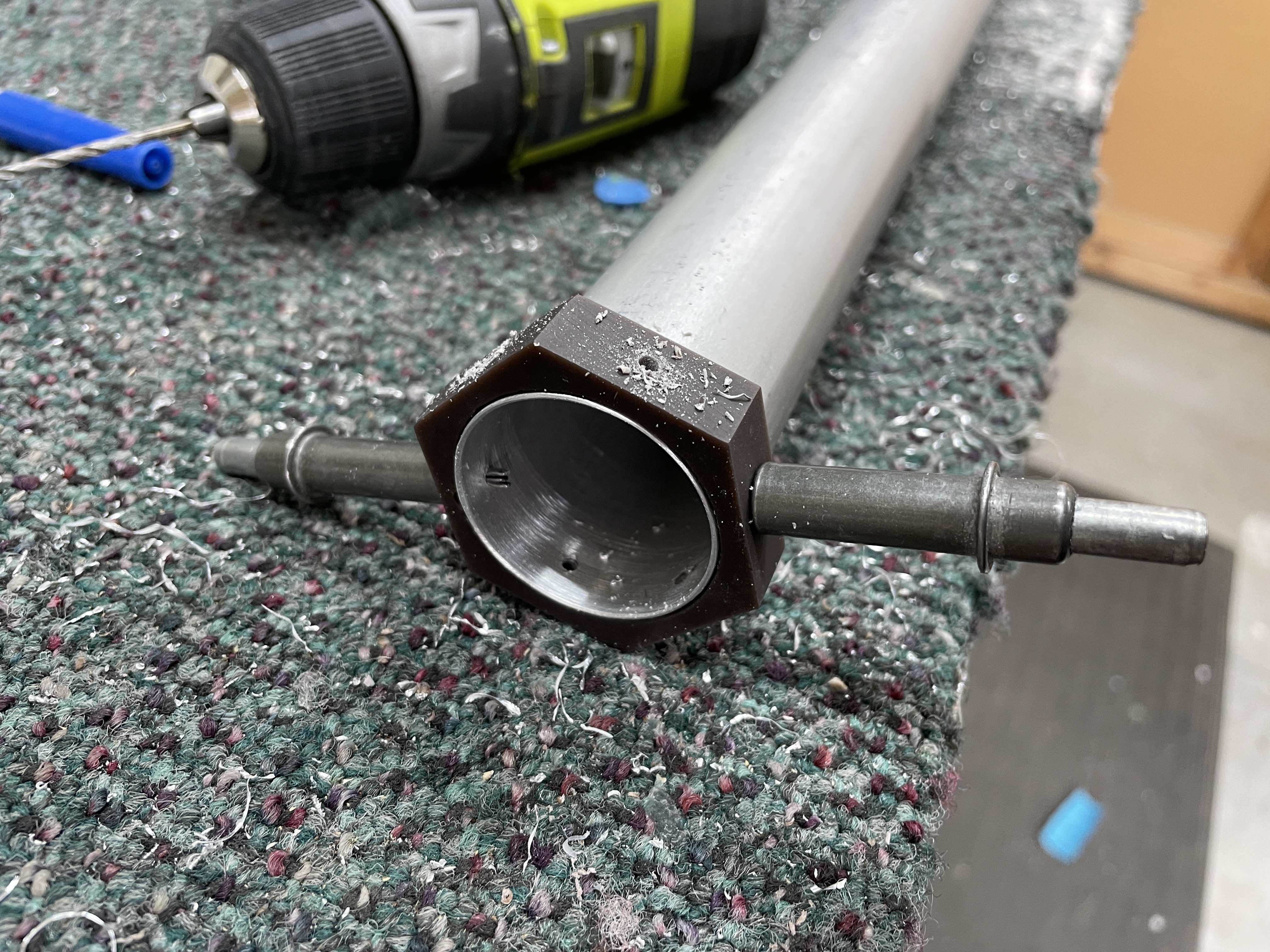
Once i had the HS out, we tried to lift it into position, only to discover i had mis-measured where the hole for the elevator trim wires exited the aft deck - so i had to de-pin the connector and remove this wire. A new hole was drilled in a more appropriate location.
 |
| The tape represents exactly where the middle spar of the HS is located - doh! |
 |
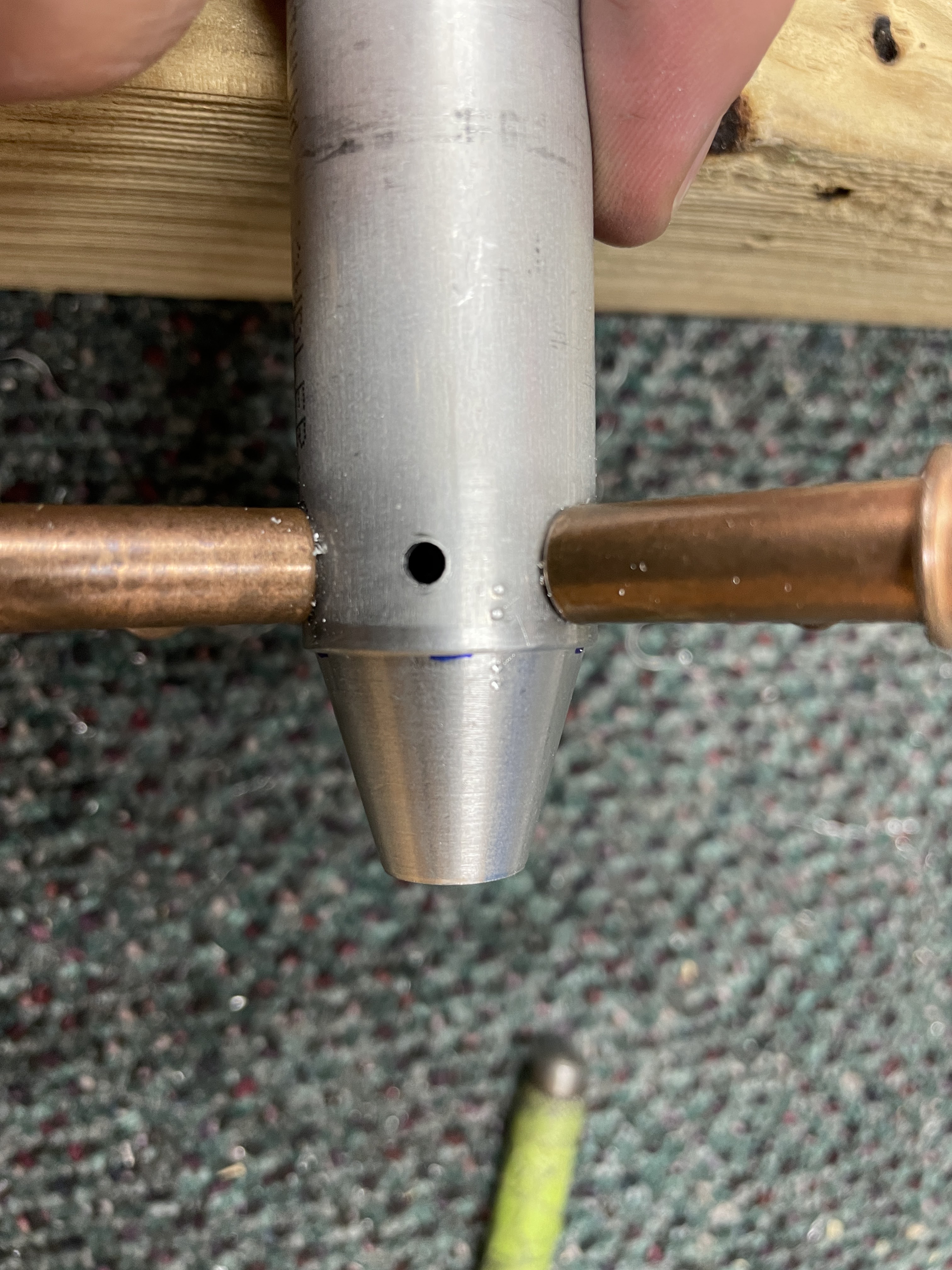
| A new hole. |
 |
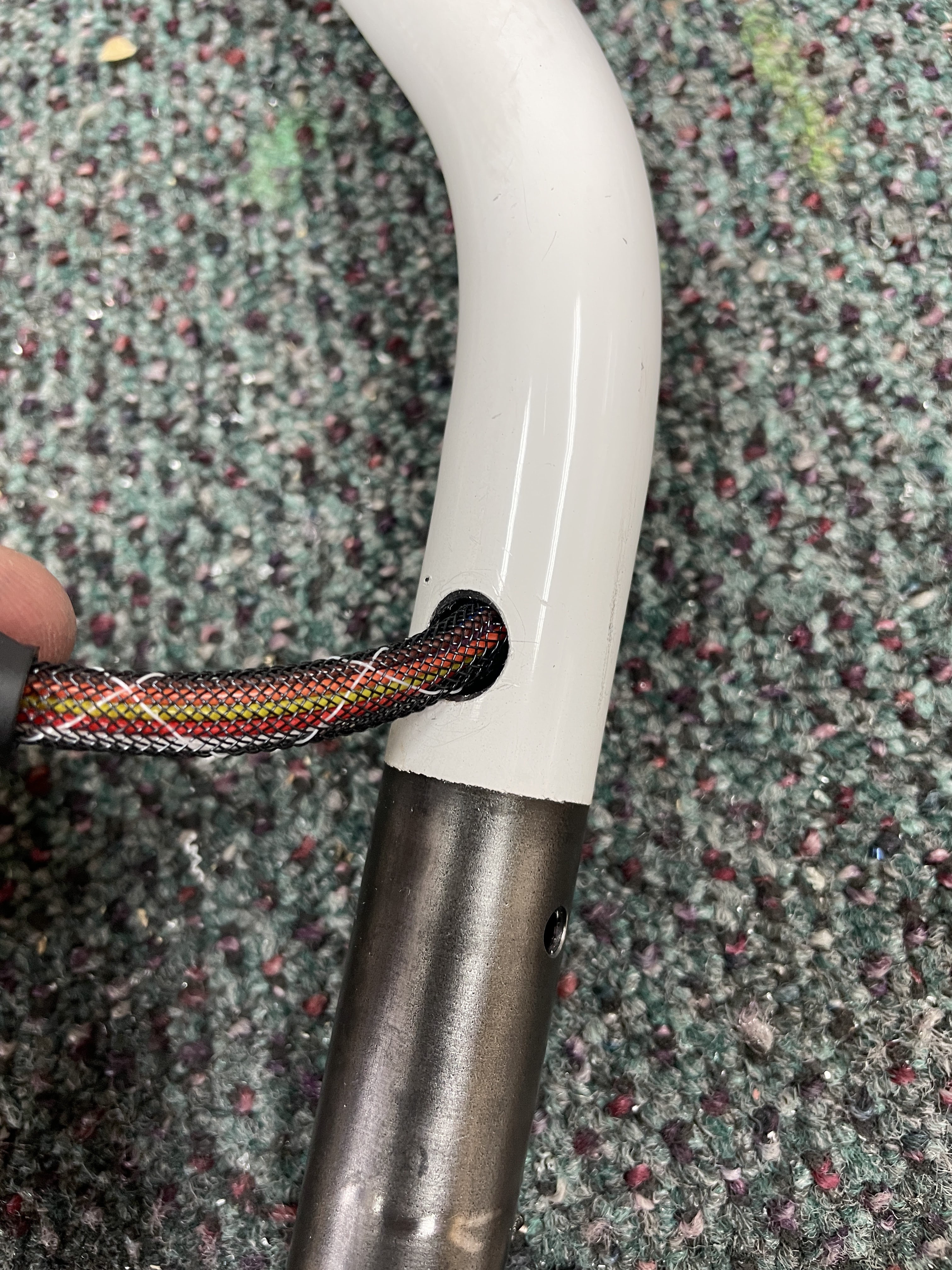
| Just fits! |
I then spent around 4 hours gently filing away the aft deck in order to get the required elevator travel. The forward travel was pretty close - this didn't need a lot of filing. But the up elevator (the aft end of the aft deck) needed a lot of filing.
 |
| Wanting to achieve the maximum travel, i was aiming for 30 degrees up, and 25 degrees down. |
The 2 forward elevator pushrods are adjusted to an accurate length during construction, and are therefore of a fixed length in the control system. The plans give you a paper template to set the angle of the elevator bellcrank, which effectively puts the sticks at the neutral pitch angle. However, this does not guarantee that the elevators are in trail. So the idea is that you adjust the length of the AFT pushrod, while the sticks are in this neutral position (using the template), such that the adjustment leaves the elevators in trail. This ultimately means with the stick neutral, the elevators are in trail.
Sounds simple!
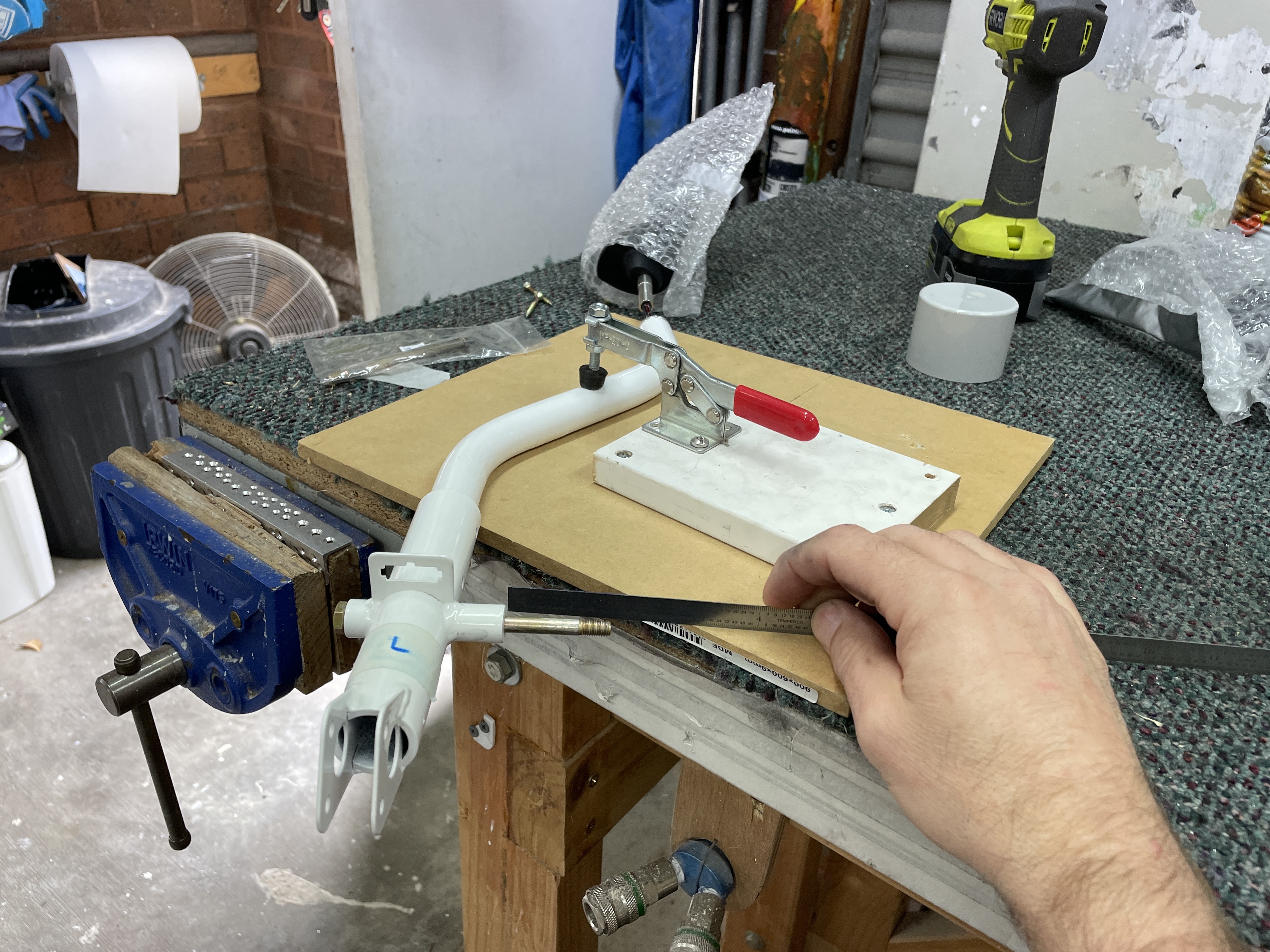
What ended up happening was that i stuck the paper template to a piece of Masonite, and cable tied it into position. I used to clamps to hold the bellcrank in the neutral position (or so i thought!).
I then clamped the elevators into trail position and compared where the end of the pushrod was in relation to the holes in the elevator arms. I measured this distance, then removed the aft pushrod and increased the length of the pushrod by the measured length. This was a very big increase in length and saw both of the rod ends at the very end of their possible adjustment (the plans call for having at least 1/2 of the threads engaged). Something seemed off here, but i persisted.
 |
| It was a long way off! |
 |
| I used a bit of card with tape on it to measure the distance. |
 |
| I then setup the pushrod on the bench, and increased the length by 1/2". |
 |
| The rod ends were marked to ensure 1/2 thread engagement |
I then reinstalled the pushrod, expecting it all to be perfect, but the controls were hitting the aft deck stops WAY before they were hitting the control stick stops. Something was not right! So i clamped the elevators in trail once again, then realised that the clamps holding the bellcrank in position had moved. I had adjusted the aft pushrod with the bellcrank NOT in the correct position. Doh!
My clever / fancy plan to adjust the pushrod on the bench was a failure!
So in the end, i removed the pushrod and re-set it back to the plans length. I left the jam nuts loose so i could adjust the rod ends in-situ and climbed into the aircraft. I was able to adjust the forward rod end by just winding it in/out, and the aft rod end by rotating the whole pushrod. Once at the right length, i then removed it, and did the fine adjustment to make sure the rod ends were planar / tightened the jam nuts.
A lesson learned - try and do something fancy is not always the best way. Simple is king. I got there in the end though!
 |
| Since i was in the baggage area, i was able to hold the bellcrank template in position. |
 |
| All correctly adjusted. |
Once this had been done properly, i then re-checked the control stick stops and they needed a very small bit of filing to make sure that paper was able to slip between the stop at full elevator deflection in each direction.
Job done! (finally).
Here is a little summary: