Search Build Log

Showing posts with label 18 - Fuel Tanks. Show all posts

5 Jun 2021

18-09: Fuel Tank Installation / Fuel Sender Wiring

Nutplates

Since i planned to prime the outside surfaces of the fuel tanks, i was not able to install the nutplates until after the priming was done. This was fairly straightforward however there was one rivet on each tank which could not be squeezed with the fuel pickup fitting installed. So i had to remove this, clean off all the thread sealant and then reinstall once the nutplates were installed using fresh thread sealant. 


The MS21053 nutplate was installed as per usual, by using a screw to hold the nutplate in position while the rivets were squeezed.

I did not have a yoke which would have fit in this gap - i could have used a gun and a thin bar, but it was much safer to remove the fuel pickup fitting. 


Fresh thread seal was used on the fitting. 


Fuel Sender Wiring

The plans call for a single wire from the sender screw (the sweeper arm) on the fuel senders. I decided to also install a ground wire instead of using the airframe. These 2 wires would need to pass through a tiny grommet in the spar to the aft side, so be installed in a connector to the fuselage. I decided to wrap this in 'snake skin' (expandable nylon sleeving). 

I found the best way to deal with this is to burn the ends so they don't fray as soon as you cut it. I then keep it in position using clear heatshrink over the ends. I used a heatshrink label on each end of the wire - 12mm at the ring terminal end, so the heat shrink helps to give some support to the wire installed in the terminal, and 6mm at the other end (as this will terminate in a pin in a connector to be decided).


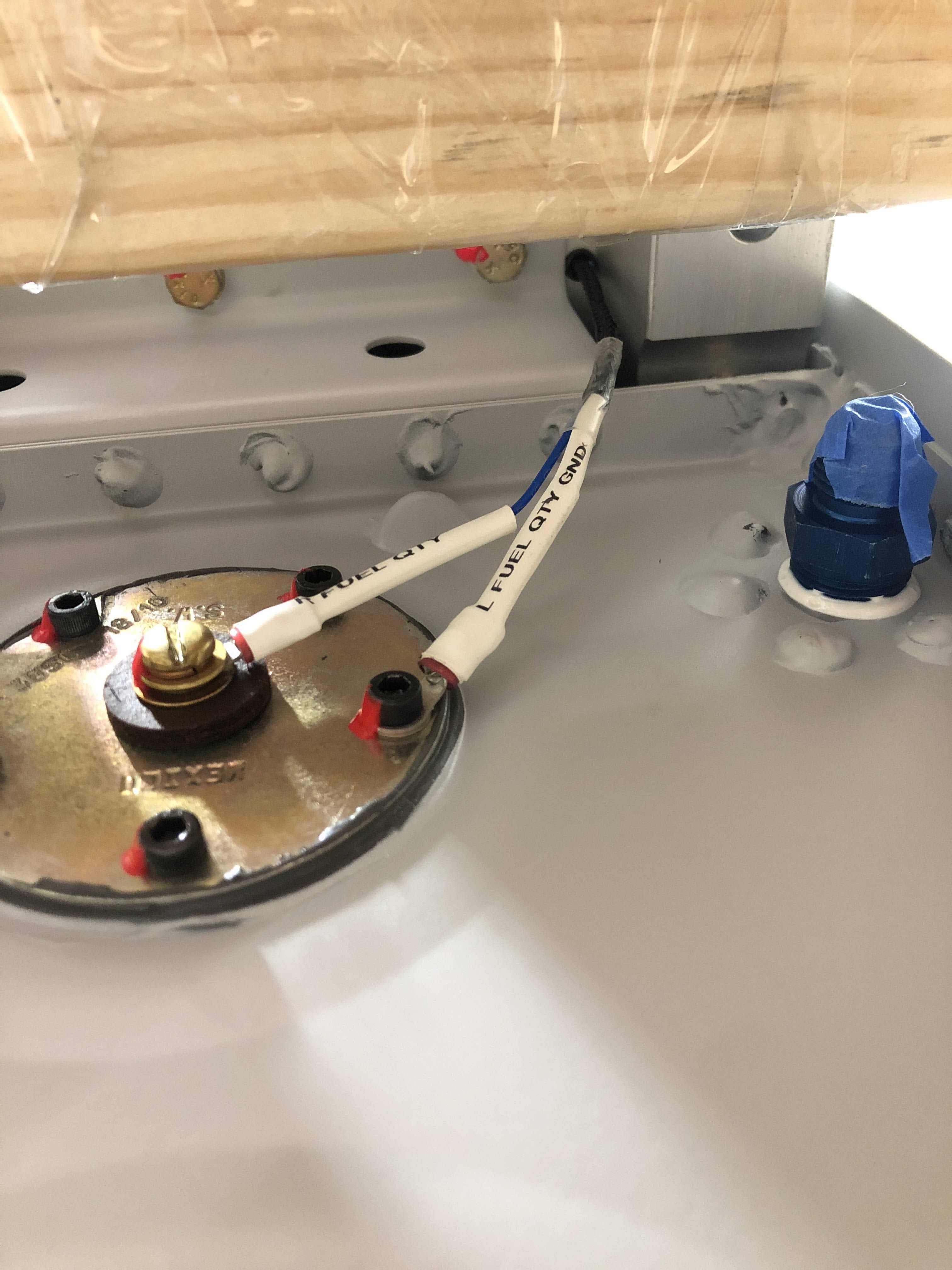
Once the tank was installed, this bundle was passed through the grommet in the spar and secured in place with a tywrap.


Tank install

In order to install the fuel tanks, i could only do it with one wing in the cradle at a time. I put some pillows at the bottom of the cradle just in case, then gently lifted the tank into position resting on the cradle. I used some timber standoffs on the rear spar and lifted the tank very slowly, one click at a time with ratchet straps until it popped into position. 

This was the setup:


I was able to very slowly, one click at a time, lift the tank into position using this method. I was very happy with the results.


The dimples held the empty tank in place with no problems - however, i loosened off the ratchet straps to if the tank fell at any stage it would be caught by the straps and not land on the cradle. 

This turned out to be a good idea - both tanks needed to be filed at the skin edge which butted up against the outboard leading edge. To get the tanks off to do this required a bit of effort - once it had popped into position in the dimpled it was very hard to remove. After MUCH head scratching, the best method was some light tapping on the aft skin edges using a piece of timber and a mallet. Very light! eventually it popped off, fell and landed in the straps. 

A little bit of material needed to be taken off the end skins of the tanks. 

It's better to be lucky than good!

Once it was refitted, I began by installing all the bolts 4/5th of the way in - they were just touched up, but not torqued. Each bolt received some TefGel to prevent any galvanic corrosion.


 The screws started at the leading edge and went top/bottom until the trailing edge. The screws were not completely tight - just almost tight. Each one also got some TefGel. 


I finally got a use for my speedbrace! This this is great for lots of screws in a row - but you really need to keep pressure on it. I found a normal screwdriver was much better for the final tightening. 

Once all the screws were in, the bolts were torqued. I measured around 8-10 in/lbs across all the bolts, and the torque tables required 25-28 in/lbs, so i went with 35 in/lbs on each bolt. 


The screws were then tightened top/bottom along the edge, and from outboard to inboard along the trailing edge, using a normal screw driver. 

I was very happy with how the tank fit - a true testament to how good this kit is. The only misalignment was between the leading edge skins and the tank skins - there's a little step up to the tank skin. I assume this is due to the skin thickness difference between the 2 skins - the leading edges skins W-00001 are 0.020" and the tanks T-00001 are 0.032", so i assume there is nothing i can do about this. 

Some stats

The fuel tanks were started on 10 Sep 2020 and was completed on 15 June 2021 - that's 278 days, or 9 months and 5 days. They certainly do feel like my babies! 

There were 1,487 rivets in the fuel tanks. 

The total amount of sealant used was tracked here


Parking the wings for a while

I removed all the blue film from both wings and they were placed back into their cradles for safe keeping.


31 May 2021

18-09: Priming Fuel Tank External Surfaces

Since i could not prime the insides of the tanks (for obvious reasons), I let the tanks sit for around 3 months, then cleaned, etched and primed the external surfaces of the tanks (excluding the external skins). I need to get some AN fitting plastic caps to install on the tank fittings. The water balloons are not good and were disintegrating. 

I masked off all the 'holes' so that water, cleaner, etch etc did not get inside the tanks.

I also protected the bearings so nothing got in. 

Everything was masked off before priming


I need to install the fuel sender signal and ground wire (and protect this with some snake-skin etc), as well as install the nutplates. Then i can install them on the spars.

Happy with how these turned out.


11 Feb 2021

18-09: R Fuel Tank Leak Repair

Well, this was a bit of a journey, but i will try and logically lay out the steps i took to repair the leak in the right tank. 

Cause

The first comment is what i believe to be the cause of my issues - when i was placing the baffle down, it was aligned such that the baffle was hanging over the root end of the rib (where the leak ended up) by perhaps a quarter of an inch. I did not do a good job aligning it with my fingers when i dropped it down into place. I did not think it was a good idea to lift if off again, as it had come into contact with all the carefully laid down sealant beads, so i just pushed it gently outboard to align all the holes. 

This meant on the root end, i was pulling the bead at that end (which had stuck to the web of the rear baffle) away from the end rib flange. It is my belief that this is what caused my issues - so for anyone following, make sure you extend your fingers and align the baffle with each end when you drop it down

1st Try

As mentioned in this post there was a small open section in the sealant which was in the same location as where the leak was, so i made an assumption that there was probably where the leak was stemming from. 
I believed this to be the offending location

So i had to cover this area with sealant. Luckily, this was quite close to the location of the fuel sender hole - so i removed the sender screws and cut the sealant bead around the sender flange with an exacto knife. I then used a pallette knife to gently pry the sender out of it's bead of sealant. 

Once it was off, the sender, the rib flange and all the screws and lockwashers were all cleaned of sealant using scrapers, a toothbrush and acetone. 

In order to ensure that any additional sealant would stick, i used a rag soaked in acetone on my finger to get clean the existing sealant. I was able to reach this area with my finger. 
A piece of aircraft canopy made into a scraper

The sender after removal

The offending area after cleaning up with acetone. 

Once this was done, i applied as much sealant as i could to this area. I found the easiest way was to just put a blob on my finger and squeegee it into place. 

Here you can see the location of the additional sealant and how it has definitely covered the offending location. It was spread along the flange as far as i could reach with my finger in each direction. 

2nd Try

After 5 days to let the sealant cure, i set up the manometer again - and she STILL LEAKED in the same location as before. The manometer was showing a solid leak. 

I was honestly surprised and confused at to how this was possible. I decided to get the borescope back into the tank to have another look. The only section which was still exposed from the original sealant application was in the corner, adjacent to the fuel drain location. I was unable to get sealant into this area the first time around because my finger didn't reach. 

So i had to get creative - in order to clean this area before further sealant application i bent a plastic toothbrush handle using the heat gun, and was then able to get inside to clean this area. To actually apply the sealant, i was able to snap a tongue depressor in 2, and tape it to the end of my finger. This allowed me to get to the corner to smear sealant into that location. 
Using the bend toothbrush to get into the corner.


The fuel sender was cleaned up again, sealant reapplied and the tank closed up. Fingers crossed once more. 

3rd Try

After 6 more days to cure, i came back to the tank and was AGAIN distressed to see that the tank was not holding pressure. However, this time the leak was not in the same location along the rib flange - it was leaking out of the flange of the fuel sender!!! 

I must not have sealed this correctly. So, time to remove it again! 

It was resealed properly this time after a good cleanup of all the flanges and the screws. 
Sealant is applied to the rib flange

The screws are ready to go with Loctite 565

I remade the sender ground wire as the locknuts had damaged the terminal after no many repeated installs. 

The sender installed (hopefully for the last time). 

4th Try

Finally, after 4 more days to cure, i went back to the tank and set the test up. THE PRESSURE SEEMED TO BE HOLDING! 

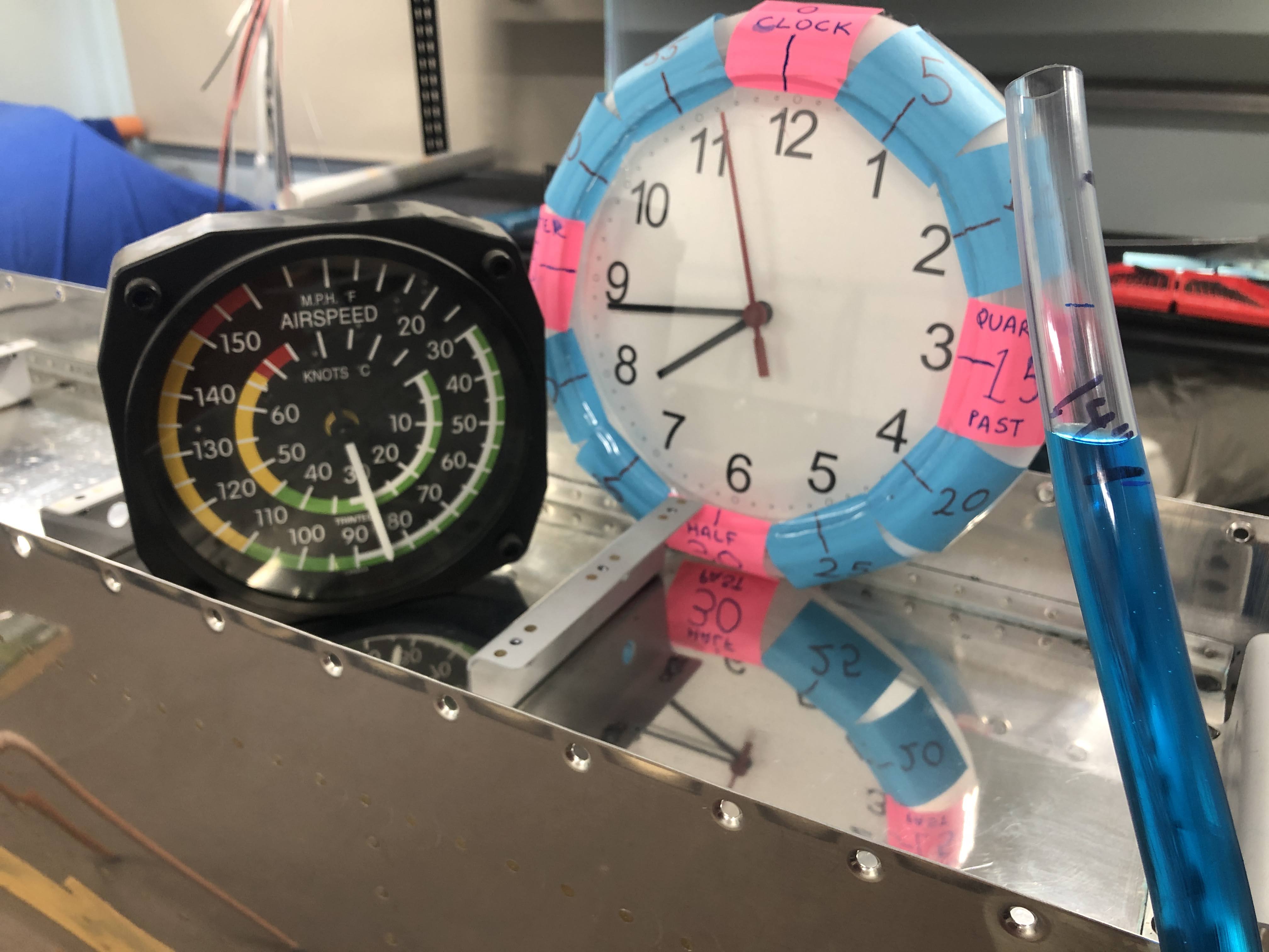
I left the tank for a while to make sure it was all ok, but the temperature in the shed was increasing that day and the manometer flowed over - in fact, it squirted blue liquid all over the walls and the storage shelf, staining my left wing top skins! (doh). Not to mention a big blue stain on the carpet. Oh well. 

I waiting until around 8:45 PM and setup the manometer again. 
8:45 PM - 30c and just above the line. 

Came back the next day:
7am the next day - 21C and the level has dropped a lot. 

9:30am - temp has risen to 23C and the level has risen

10:30am - temp is now 25c and the level risen even more.

11:30am - temp now 26C and the level still rising

12:10pm - now 28C and not quite up to where it started

12:30pm - 27C and up to the same level.

It should be noted that the water level got back to the same level as where it started, but the temp was 3-4C lower than the starting temp. During this time there was about a 3HpA drop in atmospheric pressure, so i assume to accounted for the additional help to rise back up to the line with the lower temperature. 

Having said all this, i am happy to confirm that FINALLY:

Postscript

Ever wonder what the 1psi does to the tank during testing? I was surprised how much flex the tank has. This was taken at the point in the video above right before, then after the manometer flowed over and released all the pressure: