As mentioned in a previous post i used a bench jig to set the long and short pushrods to the plans dimensioned length(s).
The next step was to install them into the aeroplane and check the rigging.
There was an amendment to the plans in 2020. The old method (plans revision 0 from 2013) involved using a supplied aluminium jig on the end of the aileron to set the neutral position.
Plans revision 2 from 2020, changes the method to match that of the RV10 - basically, the new process is:
Install the flap and make sure it is hard up against the spar (in the cruise, reflex position). With the wings vertical nose down in the cradle, the flap does this naturally)
Align the aileron with the flap and clamp in position - i used a 3D printed jig to do this.
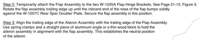
Set the aileron bellcrank in it's neutral position using a supplied jig.
This is the 3D Jig which i designed and my dad printed for me. He did one per wing.
This holds the aileron perfectly aligned with the flaps.
I noticed that with both my wings, with the flaps hard up against the spar there was a very small misalignment in chord between the flaps and the ailerons. Basically, if looking at the flaps from underneath the wing, the trailing edge of the flap was about 1/32" forward of the aileron trailing edge. The only way to align these was to move the flaps about a credit card thickness off the spar. This allowed for perfect alignment. I used a hotel card under each flap forward nose skin to hold the flaps in this position, and did my aileron alignment in this position. (For final setup, i will set the flap motor to stop the flaps in this position just shy of the spar).
Once you have this setup, the correct rigging is achieved when the small steel pushrod is adjusted to fit (i.e. you adjust it to fit between the aileron held in the neutral position with the flaps, and the aileron bellcrank held in the neutral position by the jig).
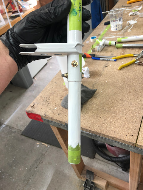
The long aluminium pushrod is adjusted so that the forward torque arm is 2 17/32" from the fuel tank end rib skin and the centre of the bolt hole in the arm.
To check this rigging, the pushrods had to firstly be installed. When installing these, i used the supplied hardware callouts, however in some cases added a thin washer, or used a combination of thick and thin washers to ensure proper fitment. The bolts were installed using temporary nuts so i could check the rigging, then when i found it was correct, i added a locknut and torqued each to 38 in/lbs. Each one was marked with torque seal. I then tightened all the jam nuts, made sure the pushrods had proper movement, and marked the nuts with torque seal.
Left wing bellcrank jig held in the neutral position
Left wing bolt hole 2 & 17/32" from fuel tank skin
Left wing - chord wise flap / aileron alignment
Left wing - span wise flap / aileron alignment
Right wing - bellcrank jig in place
Right Wing - bellcrank 2 & 17/32" from flap rib skin
Right Wing - Chordwise flap / aileron alignment
Right Wing - span wise flap / aileron alignment
With all the rigging completed, there was nothing left to do other than make aeroplane noises:
At the root end of the wing, is a steel torque tube assembly which takes the motion of the sticks and transfers this aft to align with a lightening hole just aft of the spar. The long pushrod then takes the motion to the bellcrank, which turns it 90 degrees and uses the small steel pushrod to move the aileron.
The torque tube assembly consists of a large end on the forward side of the spar, and a small end on the aft side of the spar. These are joined with a piece of steel pipe which goes through a hole in the spar.
The first step was to deburr all the holes, and install the tube ends (threaded inserts). Again, these did not fit and i had to reduce their diameter using the drill press method. The ends of the tubes had some pretty crappy power-coating, so i cleaned this up.
The filing of these parts really gummed up the file - so here is the little DIY tool i made from copper water pipe to clean my file.
Once the ends fit in the tubes, they were match drilled to #30 and marked so they can be placed back in the same positions.
The drill press and vblock was used for the first hole.
The second hole was done on the vice with a hand drill.
The steel tubes which join the forward and aft parts are called the "torque tube collars". These were cut to length roughly with a hacksaw, then filed back to a tape line to make sure they were accurate and square - although i don't think the length is very critical here. A line was marked 1.5" down from one end of the tube and it was match drilled #30 to the forward torque bracket. Once match drilled and clecod, i up-drilled the holes using a 3/16" reamer (for an AN3 bolt). I went slowly and carefully from one side, then continued reaming the other side from the inside out. Since there was already a #30 hole, i was able to look down this hole and align the centre of the reamer with the hole to ensure the hole drilled was straight. This meant i was then able to install the AN3 bolts with temporary nuts.
I made sure to lay out all the parts, so as not to make a mistake and drill the tubes to the wrong part.
Again, the tape helps to keep the cut square and to the correct length when filing.
A reamer was used to drill the bolt holes.
Temporarily assembled for the next step.
Next up, you are supposed to move the small torque tube part along the tube to achieve a dimension from the faces of the threaded tube inserts. This dimension is very tight - from 17 3/4 minimum, to 17 25/32 (or 450.8 to 451.6 mm). That's a tolerance of 1/32" (or 0.8 mm). How to do this???
What i did was place a piece of tape on the bench and i measured two lines that were right in the middle of the range - these were 451.1 to the outside of the marked lines.
To make the actual measurement of the parts to this guide, the arm of the forward (smaller) torque tube part needs to be clocked so it is raised off the bench, when arm of the aft torque tube assembly is clamped to the table. The arm needs to be raised 1 1/64" measured from the table to the outside face of an AN3 bolt placed in the holes of the arm. So i cut a block to be 1 1/64" and marked where the bolt needs to go to be located at the part of the block which was exactly this dimension.
The bolt needed to be aligned within these marks on the block
Once the arms are setup as above, i was able to place the assembly on the table above the marks made previously. I used a square to align the faces of the tube ends to the outside of the lines. I then made a line around the un-painted steel collar marking where the aft tube needed to be located on the tube. It just didn't feel right making these assemblies to an accurate dimension, but not fitting these to the actual wing? So i took the assembly to the wing for a test fit, and making sure the tube end threads were fully seated in the bearings, i was able to mark the steel collar with the assembly at this dimension, and compare them on the bench.
Aligning the faces of the tube ends with the outside of the drawn lines to achieve the exact dimension.
Here you can see the difference between the plans stated dimension, and when the tube ends threads were fully seated in the bearings - this is the left wing.
Measuring how many washers.
Once back on the bench, i had 2 options - drill the tube to take up the extra space as above (i.e. move the small assembly further along the collar to increase the dimension before drilling), or follow the plans and install washers to take up this space. On the left wing, I elected to used a single thin washer on each end of both wing assemblies to take up this space.
One thin washer at each end between the face of the tube end and the bearing.
For the right wing assembly, when doing the fit up, i placed a thin washer on each end of the assembly. In this case however, there was no gap between the plans stated dimension - in fact, to fit washers on this assembly, i needed to shorten the plans stated dimension by about 1 thin washer thickness.
Here you can see, with one washer at each end, only half the line is visible (the line was marked at the plans stated dimension).
This meant when setting up this tube for drilling, i set it up with half the blue line showing. This shortened the plans dimension very slightly, and allowed a thin washer at each end.
I was happy with this approach - rather than just blindly following the plans dimensions i was able to fit each side perfectly to the wing assembly and got to use one washer on each tube end.
Next up, once each tube was setup again correctly, one hole was match drilled from the small forward torque tube assembly and clecod. It was then removed and the other holes drilled. They were then all drilled up to 3/16" using a reamer, using the same method as previously.
Preparing for final assembly
Since these are steel parts, the plans state you must prime the insides of the powder coated parts, and the inside and outside of the steel collar. The steel collar is a very tight fit however, and i thought if i added primer to the outside of the steel collar, or the inside of the torque assembly where it was supposed to slide into, it would never fit.
When fitting the assembly to the wing, the steel collar is bolted to the aft (larger) torque assembly before fitment. So for this end, i elected to install the steel collar with the primer wet, as there is really no need to ever take it apart. At the other end of the steel collar however, where it slides into the forward torque assembly during final installation, i had to mask the collar to prevent paint going onto the outside at the end. I also didn't put any paint on the inside of the forward torque assembly.
The primer used was Norglass ShipShape again, and i painted it into the tubes using a throw away brush. The first step was to install the tube ends and i did this wet.
The ends were installed with wet primer and rivets set.
I was then able to apply primer to the inside of the steel collar and the outside where it slides into the aft torque assembly. Bolts were placed in to align the parts while the primer dried and nuts torqued. I then painted the outside of the steel collars, but not the ends which have to slide into the forward torque assembly during installation.
These were installed wet and the bolts placed in position to align the parts.
Nice coverage inside the parts
I was very happy with how these turned out... until tomorrow at least!
Oops.
The next day, once the paint was dry i did a test fit into the wing and realised i stuffed up. As you can see below, in order to get the parts into position, the forward torque assembly must slide way down the steel collar (at least another 2") to allow the parts to be rotated into position. Once in position, the forward torque assembly is slid back along the tubes and the ends placed in the bearings.
Since i painted mine all the way up to the final position, i was not able to slide these tubes down the collars during assembly. DOH!
Here you can see, with the parts in the final position it is not possible to install them. The forward torque assembly needs to be slid down the collar (the paint has already been removed in this photo).
So that meant i had to break out the acetone and sand-paper and remove some paint. Luckily this paint sands really nicely.
The paint here did not allow the assembly to slide down the tube enough.
So, off some came.
This allowed the tubes to be installed by sliding them down the steel collar, and then back up the tube to the final position. I used grease on the inside of the forward torque assembly, and on the steel collar for final assembly. For the now exposed piece of steel, i used some boelube to prevent surface rust over time and i have added this to the list of things to check at each annual inspection.
In final position, but with no bolts installed.
TefGel was used on the shanks (not the threads) of the end fittings. Ignore the green paint on the steel collar here - this also prevented installation so was removed as well.
I used a lithium based grease with teflon (PTFE).
Both tubes installed and bolts torqued
This exposed part was coated in boelube and will be inspected at each annual. If i were to paint this, it would be impossible to remove these parts.