Search Build Log

Showing posts with label OP - Finish Options. Show all posts

3 Sept 2025

First panel layout / Learning CAD / Learning Inkscape

Van's has a download page where you can download a CAD model of the RV14 panel assembly.  

I brought this into OnShape, and downloaded the Garmin 3D model file. Many other items were downloaded from Digikey and other online sources. 

This allowed me to add the components where i thought they would work, and checking clearances etc for everything. 

https://cad.onshape.com/documents/5f5ee2891f0981db33ca13ea/w/d10e34a47ff7dc421ab9c555/e/eedb206e900f1290f0f90ed2. 

As a test, mostly because it was a cool thing to do, i exported the faces of the Left/Centre/Right panels as .DXF files, and sent them off to a local laser cutter. It took only about an hour and they fit PERFECTLY! I test fit some of the components i had on hand, and was honestly amazed that everything slotted in with no issues.


This was V1 of the layout. I stuck it up in the shed for motivation.


This is how my custom dimmer board fit:


Buoyed by confidence, i decided to start adding labels. The workflow to do this is as follows:

  • In Onshape, create a 1:1 scale drawing on A2 sized paper of each panel. Once this is created, it can be exported from the drawing tab as an .SVG (Scalable Vector Graphics) format. 
  • Open the .SVG in Inkscape, and spend some time to remove any unwanted little elements (like stray circles or standalone nodes etc), and then use the 'Union' tool to group together all the lines which make up one element - for instance, one switch cutout hole got all the lines 'unioned' (unionised?). 
  • Once the base drawing was tidy, i mark this as a 'hairline' width line, and make it pure red. This will be the cut-lines where the laser cuts through the panel all the way. 
  • I then made a new layer, and started adding my graphics. This is done as lines which have a stroke applied, along with text. 
  • I then added the GDU460 screenm G5 and the start button as plain images and sent the graphics off to be printed in color on some card. I was honestly surprised that everything lined up perfectly!

With all the switches installed, and hte G5 mocked up using some foam to the correct thickness of it's bezel, i was able to test to see how my switches worked:


With all the switches installed.

This shows how close the fingers are to the G5 - this is a close as i wanted to get.


The issue with this layout was discovered when i had one of the fuel pump switches in the top row off, and selected the engine PRI/SEC switch on below it - there was not enough room between the switches when they are both of the locking variety. These were vertically spaced at 35mm - which was not enough. 


So i went back to the drawing board, moved some switches around and re-made both the 3D model, as well as the Inkscape label drawing. I realised that i could output the labels file from Inkscape as a .PNG (with a translucent background), and add this as a 'decal' in OnShape to the 3D model of the panel. 

This is the result, and validates that the Inkscape drawing matches the 3D cad model perfectly. 


This switch layout solves the issue of the switches not having enough room between them - if the lower switch is not locking, then 35mm spacing works great. 


I also made up the lower Circuit Breaker panel as a test:


The next step will be to make a decision on what type of finish i want for the panel. The most traditional would be an anodised (black) surface, with the labels laser etched. Other options include a plain painted panel, with the labels UV printed on top. Or i could go really flash, and design a full-on graphics overlay for the panel which gets printed to the panel once it's been laser cut. 

Before the final laser cutting and etching (if i choose not to have them printed), the files need a bit more work:

  • All text and lines must be converted to outlines - aka a single path which encompassed the outside shape around the stroke. 
  • These have no-stroke applied to them, but are all filled. These get raster engraved by the laser cutter.

So many choices! Like everything - it will come down to cost!

Here are some cool examples of totally UV printed panels.


This is probably my favourite. I like the honeycomb.


7 Jul 2025

Main Fuse Block Location / Avionics Mounting Shelves

Fuse Block Locations

My system design (which i have been working on) will have 2 fuse distribution blocks. An 'Engine Bus' which will run all of the SDS components, and a 'Main Bus' which will power all the non-essential items, plus the secondary avionics feeds. There will also be an 'Essential Bus' which will be the primary avionics input power (and consist of traditional circuit breakers). 

The 'Engine Bus' and 'Essential Bus' breakers will mount on the lower angled 'power module' location in the centre tunnel area of the cockpit. 

The 'Main Bus' will consist of a 32 position Bussman RTA Fuse Block (15712-16-16-21A). This is made for standard ATO fuses. This consists of a single fuse block, but with 2 'busses', each with 16 fuse slots. Since this bus will have a single power feed, i did not want the seperate busses. Correcting this was a simple task of drilling out some rivets on the rear bus bar, and riveting on a brass linking bar. The whole thing was then covered in 'liquid electrical tape' to help prevent anything shorting against this exposed bus bar. 

A couple of rivets were removed from each bus bar, and the little plastic seperator between the bars was removed. 

A piece of brass was riveted between to two busses, making it a single bus unit.


Since the bus bars were exposed at the back, i thought i would covered them up. 

The next question was where to mount this unit! Ideally, it could be accessed on the ground without too much trouble (pre-flight etc), but somewhere not conspicuous (i don't need access to this in flight). The best place seemed to be somewhere on the sub panel. The right side has the map box, so the left side was the best location.

The fuse block mounts from behind a panel, and looks pretty neat. For ease of maintenance later on, i was initially thinking this should be mounted on a removable panel. I could then unscrew the panel, to get access to the back side for removing or changing any wires etc. So i began by making up the mounting panel from some scrap. 

Initially the mounting holes were drilled.


Then the hole cut out in the centre.


Minimum edge distance was respected and the panel marked for cut out.

This looks very neat once mounted.

Note, the busses had not been joined in this photo yet.

To make sure the panel was not going to interfere with the canopy when it was closed, i made up a cardboard template which represented the canopy frame. I then placed the panel in various locations to work out the best place for it. In the end, i realised that the large panel would result in a very large hole in the sub panel, and it really wasn't required. I could mount the fuse block directly to the sub-panel, and if i needed to access the back side, just allow a service loop big enough that the whole panel could be dropped down and forward. 

Since i had the panel made up, i used it as a template to cut the hole in the sub panel! 
The cardboard represents the canopy frame position.


The fuselage rotisserie came in handy once again!

The mounting holes are not equidistant from the ends of the block - by mounting it this way (upside down) the mounting screws will locate on the flat part of the panel (not on the lower angled part).

I procrastinated about this for a loooooooong time!


Once the template was mounted, i drilled radius holes in each corner.


This was NOT fun!


The final product looks pretty good, i think.

Mounting locations for Other Avionics

While i don't really know what other avionics i am going to need, i decided it was a good idea to make some locations for it all to go! Once again, access for maintenance was the primary requirement. I settled on two seperate locations. 

Left and Right Avionics Shelves

 On the right hand side, between the sub-panel and the firewall was a good location for mounting avionics It was be access through the 'map box' hole fairly easily. On the left hand side, there is no real access to this area once the top forward skins are riveted on. 

As many others have done, my approach was a couple of shelves which are held on by hinges at the forward ends, and by a couple of pan head screws at the aft ends. The hinge pins extend into the centre section, which can be accessed through the OP43 - Avionics Access Panels, and pulled out. This would drop the whole shelf from the aircraft. Alternatively, the screws can be removed at the aft ends, and the panels hinge downward. I will place the connectors for any avionics boxes mounted here on the aft sides. 

The panels were made from 0.032" sheet, with some spare J-Channel as stiffners underneath (left over from the wings)


The forward side hinges rivet to the firewall stiffner.


The hinge pin extends into the center section, so it can be removed it required to drop the whole avionics shelf out.


There is a convenient cable tie hole in the adjactent rib to hold the hinge pin.

The J-Channles were modified on the front ends, so there were no sharp corners above your knees.


The front lips of the shelves were bent to match the angle of the sub-panel flange.


This is an example of how avionics boxes will mount to the shelves. The stiffners help to stiffen the shelves, but the avoinics boxes themselves will also help. Generally the avionics boxes would be mounted with the connectors on the aft edge (right panel above) for ease of removal from the cockput side. For a radio like this however (left panel above), which is in a rack, it would be mounted the opposite way - as the radio itself would slide out of it's rack into the cockpit.


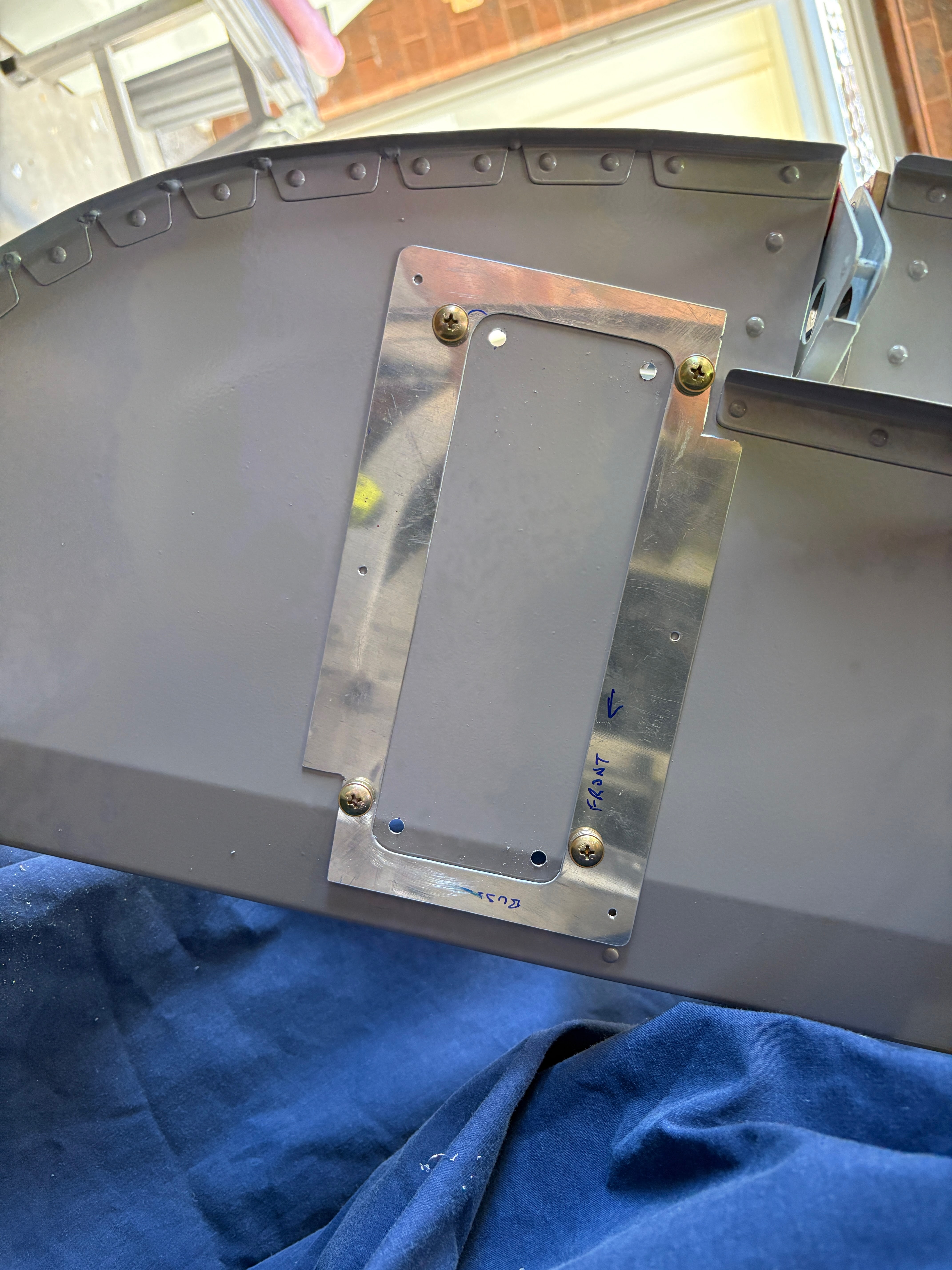
One existing nutplate hole was utilised for the forward attachment to the sub-panel flange, and an additional hole was added inboard.


The old AN3 nutplate jig was used.


Couldn't get in here with the squeezer so used a LP4-3


Here you can see the forward mount - i will use button head hex cap screws instead of bolts.

Everything was primed, the mount plates and stiffners dimpled, then riveted together.


Centre Section Avoinics Mounting

For the center avoinics mounting, i chose to use the left over C-01442B canopy alignment channel, attached to some angle brackets which were riveted to the ribs on each side. The channel will be held in place with socket head cap screws, as these are more easily screwed in than regualar screws, when reaching in through the avionics access panel holes. 

The bars were spaced to mount the GEA24 (Garmin EIS) - but i envisage these will be useful for a number of different things! (i hope). 

The brackets were held the correct distance apart (for the GEA24 mounting) with a sacrificial sheet then match drilled to the ribs.


This shows how the mounting channels will span between the brackets.

This shows how the avoinics would mount. The bars would be removed and taken out of the airframe, and have nutplates installed to hold each piece of avionics.


Nutplates riveted on


The socket head cap screws are great - they can be screwed in with a ball-end hex driver, which does not need to remain aligned with the screw.


That is it for the avoinics mounting for now - more to come later!