As always, the first step is drilling and/or countersinking. In this case, it was the battery box. This is held together at the bottom with flush rivets, and is also riveted to the firewall with flush rivets. I had to be quite creative with the countersinking!
 |
| The suicide countersinking tool! I went slowly and constantly checked i was not going to deep. |
 |
| I tried to use the 90 degree bit on the lower holes behind the front lip of the battery box, but could not get in straight. |
 |
| Probably should have deburred the part before countersinking! |
 |
| Ended up flexing the lower lip of the box to reach the lower holes using the long drill extension. |
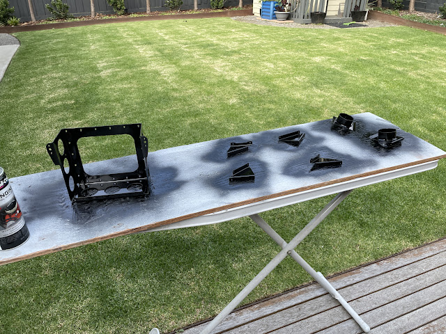
The battery and heater vent boxes were primed along with the remaining parts in Chapter 28, and then all aluminium parts which will be in the engine compartment, were top coated with black high temperature engine enamel. I riveted the battery box together before applying the black engine enamel.
 |
| I could use the squeezer on the forward 3 rivets, but could not get the squeezer onto the back most rivet. |
 |
| To reach the back most rivet, i placed my long "special elevator bucking bar" into the vice, and backriveted the corner rivet. |
To make up the vent doors, the first step is to fabricate a hinge from some stainless hinge material. The kit provided a 6" long piece of material for this purpose - I was able to cut it up using the metal Dremel wheel - the bandsaw wouldn't touch it!
One interesting point - is the plans ask you to make it up out of "MS20257-C2 Stainless Hinge raw material". However, the kit comes with a part labelled "7200x6" - this is the stuff to use.
Once the parts were deburred, i cut the hinge pin ever so slightly shorter than the length of the hinge, and closed the eyelets at the both ends a tiny amount - just enough to stop the pin falling out.
 |
| Squashing the end eyelets ever so slightly. |
The hinge door comes with an extra piece at the bottom edge, which is used to align the hinges for match drilling. I did so using some boelube and the drill at a slower than normal speed. Once drilled, the lower 'extra bit' it cut off (save this piece - don't throw it away!). Everything was deburred and dimpled and the hinge is attached to the vent door using stainless steel rivets - they were a real pain to set using the squeezer. I recommend backriveting these for anyone else following. Mine bent over every so slightly - but i decided not to try and drill them out given how hard they are.
Now, if you cleco on the hinge doors to the firewall, you will notice that the lower hinge attaches straight to the surface of the firewall. But he upper hinge, has the vent door between the hinge and the firewall surface - this makes it impossible for the vent doors to sit flat against the firewall! The undocumented solution is to use the little piece of stainless you cut off the vent doors as a shim under the lower hinge (between the lower hinge and the firewall). The following video illustrates the issue and solution:
Once the vent doors are made up, the vent arms are riveted on, also using the painful stainless rivets. The vent door assemblies are then riveted to the firewall using AN470AD3 rivets on the lower hinge. Given how thin and flexible the firewall is, i placed the manufactured head of all rivets for the vent boxes on the inside, against the firewall sheet (and set the shop heads on the forward side).
Once the doors are in position, i was able to rivet the vent boxes together. On Page 28-09 the plans ask you to rivet the vent door sides to the vent inlets using 4 x LP4-3 rivets.
However, if you read forward in the manual to the Firewall Forward chapter, Page 48-02 (or on the OP62 - EXP119 KAI, Page 62-17) it asks you to modify the right vent box, by drilling out 2 of the 4 LP4-3 rivets on the right hand side and riveting on a blanking plate.
Hence, i decided to rivet the left heater box assembly together using all 4 rivets, but rivet the right one using only the top 2 rivets. These were then riveted to the firewall, keeping the manufactured head on the aft side (as the firewall sheet itself was the most fragile).
 |
| Right side box was assembled using only the top most LP4-3 rivets. |
 |
| The aft side components - the hater cable mounts to the vertical arm and actuates the door using the arm riveted to the door. |
Finally, with my Dad's help we back riveted the battery box to the firewall. Dad held the bucking bar on the forward side (inside the battery box) and i set the rivets from the aft side. The only exception was the 2 rivets right under the firewall cross member - why Van's didn't just move them down 1/4" i will never know! For these ones we had to use the backrivet set on the front side (on the flush manufactured head) and i used the angled end of my tungsten bucking bar on the shop head.
 |
| The top 2 rivets right under the cross member were a pain - i used a bit of cardboard on the cross member to protect the paint, and use the angled bit of the tungsten bucking bar to set these rivets. |


.png)
.png)


No comments:
Post a Comment