Fuse Block Locations
My system design (which i have been working on) will have 2 fuse distribution blocks. An 'Engine Bus' which will run all of the SDS components, and a 'Main Bus' which will power all the non-essential items, plus the secondary avionics feeds. There will also be an 'Essential Bus' which will be the primary avionics input power (and consist of traditional circuit breakers).
The 'Engine Bus' and 'Essential Bus' breakers will mount on the lower angled 'power module' location in the centre tunnel area of the cockpit.
The 'Main Bus' will consist of a 32 position Bussman RTA Fuse Block (15712-16-16-21A). This is made for standard ATO fuses. This consists of a single fuse block, but with 2 'busses', each with 16 fuse slots. Since this bus will have a single power feed, i did not want the seperate busses. Correcting this was a simple task of drilling out some rivets on the rear bus bar, and riveting on a brass linking bar. The whole thing was then covered in 'liquid electrical tape' to help prevent anything shorting against this exposed bus bar.
 |
| A couple of rivets were removed from each bus bar, and the little plastic seperator between the bars was removed. |
 |
| A piece of brass was riveted between to two busses, making it a single bus unit. |
 |
| Since the bus bars were exposed at the back, i thought i would covered them up. |
The next question was where to mount this unit! Ideally, it could be accessed on the ground without too much trouble (pre-flight etc), but somewhere not conspicuous (i don't need access to this in flight). The best place seemed to be somewhere on the sub panel. The right side has the map box, so the left side was the best location.
The fuse block mounts from behind a panel, and looks pretty neat. For ease of maintenance later on, i was initially thinking this should be mounted on a removable panel. I could then unscrew the panel, to get access to the back side for removing or changing any wires etc. So i began by making up the mounting panel from some scrap.
 |
| Initially the mounting holes were drilled. |
 |
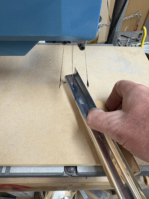
| Then the hole cut out in the centre. |
 |
| Minimum edge distance was respected and the panel marked for cut out. |
 |
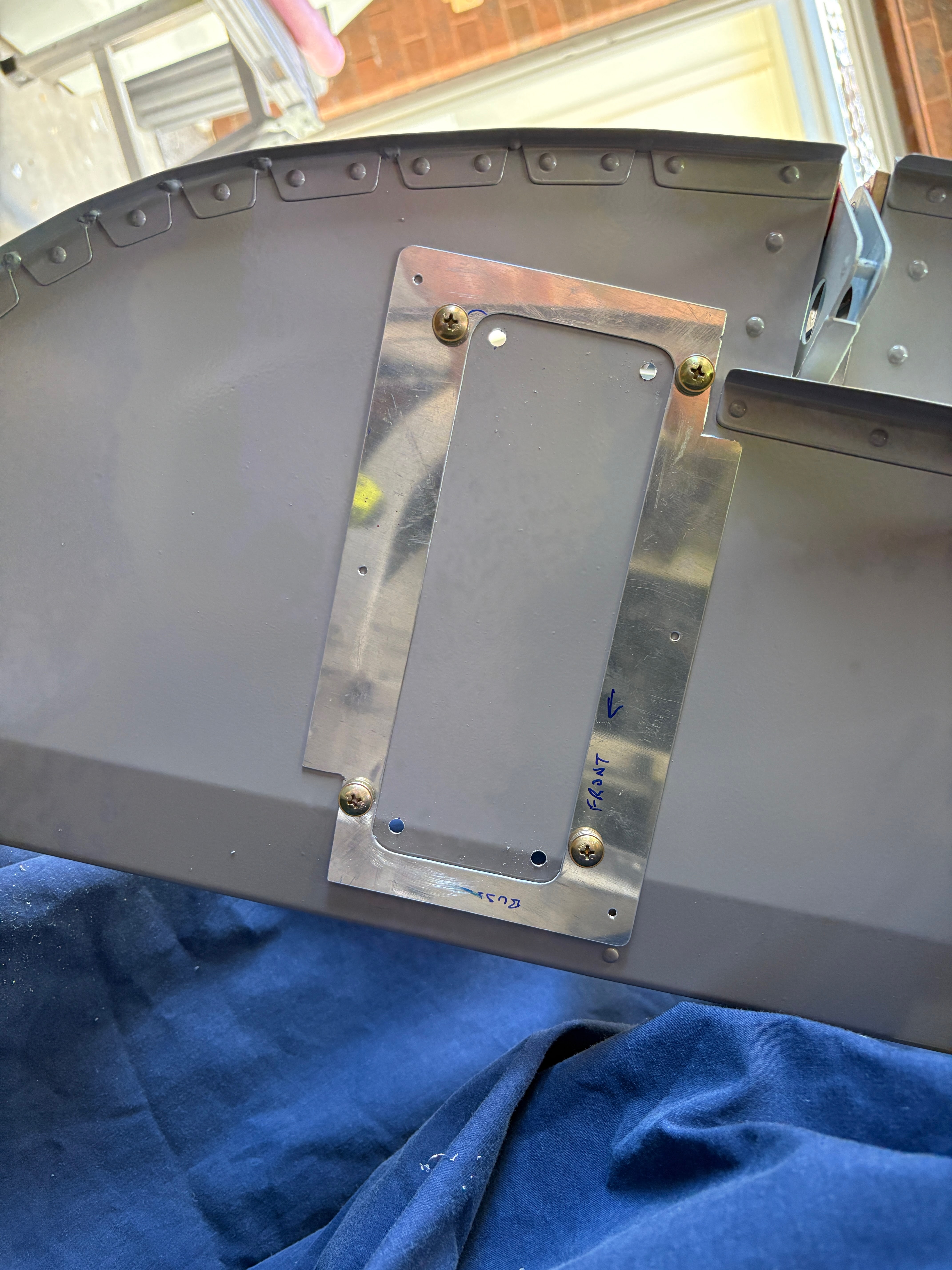
| This looks very neat once mounted. |
 |
| Note, the busses had not been joined in this photo yet. |
To make sure the panel was not going to interfere with the canopy when it was closed, i made up a cardboard template which represented the canopy frame. I then placed the panel in various locations to work out the best place for it. In the end, i realised that the large panel would result in a very large hole in the sub panel, and it really wasn't required. I could mount the fuse block directly to the sub-panel, and if i needed to access the back side, just allow a service loop big enough that the whole panel could be dropped down and forward.
Since i had the panel made up, i used it as a template to cut the hole in the sub panel!
 |
| The cardboard represents the canopy frame position. |
 |
| The fuselage rotisserie came in handy once again! |
 |
| The mounting holes are not equidistant from the ends of the block - by mounting it this way (upside down) the mounting screws will locate on the flat part of the panel (not on the lower angled part). |
 |
| I procrastinated about this for a loooooooong time! |
 |
| Once the template was mounted, i drilled radius holes in each corner. |
 |
| This was NOT fun! |
 |
| The final product looks pretty good, i think. |
Mounting locations for Other Avionics
While i don't really know what other avionics i am going to need, i decided it was a good idea to make some locations for it all to go! Once again, access for maintenance was the primary requirement. I settled on two seperate locations.
Left and Right Avionics Shelves
On the right hand side, between the sub-panel and the firewall was a good location for mounting avionics It was be access through the 'map box' hole fairly easily. On the left hand side, there is no real access to this area once the top forward skins are riveted on.
As many others have done, my approach was a couple of shelves which are held on by hinges at the forward ends, and by a couple of pan head screws at the aft ends. The hinge pins extend into the centre section, which can be accessed through the
OP43 - Avionics Access Panels, and pulled out. This would drop the whole shelf from the aircraft. Alternatively, the screws can be removed at the aft ends, and the panels hinge downward. I will place the connectors for any avionics boxes mounted here on the aft sides.
The panels were made from 0.032" sheet, with some spare J-Channel as stiffners underneath (left over from the wings)
 |
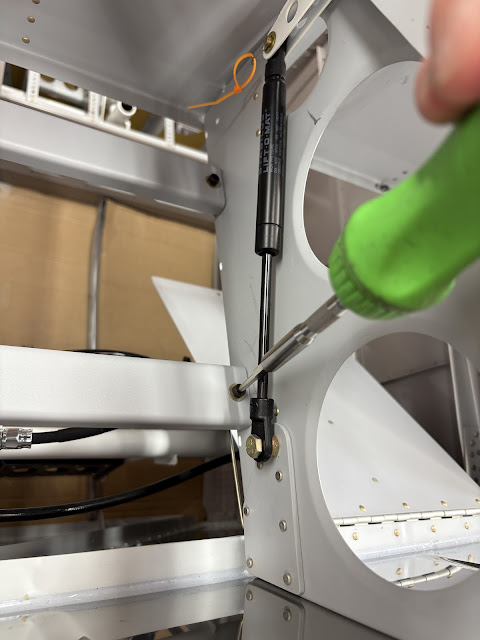
| The forward side hinges rivet to the firewall stiffner. |
 |
| The hinge pin extends into the center section, so it can be removed it required to drop the whole avionics shelf out. |
 |
| There is a convenient cable tie hole in the adjactent rib to hold the hinge pin. |
 |
| The J-Channles were modified on the front ends, so there were no sharp corners above your knees. |
 |
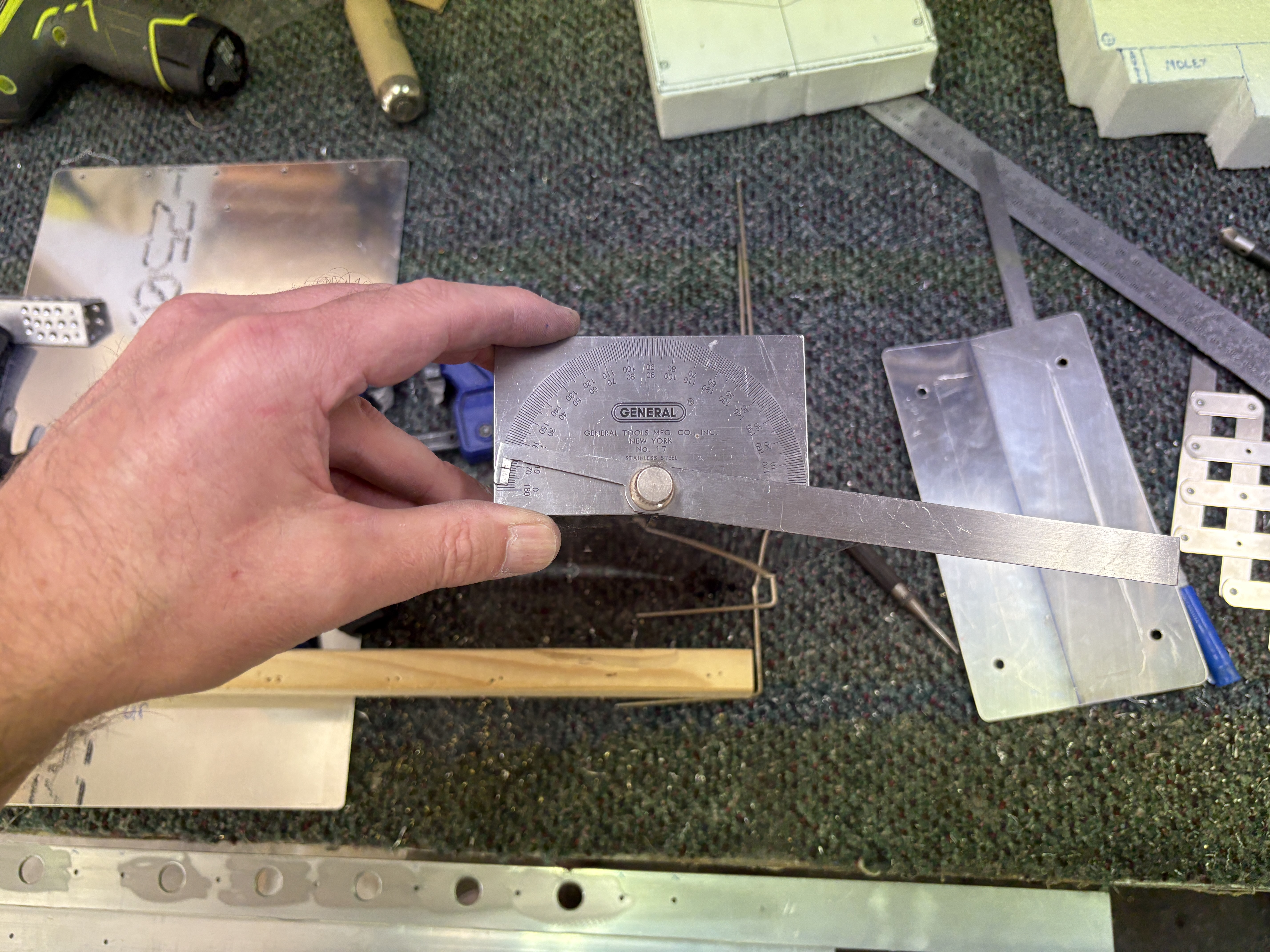
| The front lips of the shelves were bent to match the angle of the sub-panel flange. |
 |
| This is an example of how avionics boxes will mount to the shelves. The stiffners help to stiffen the shelves, but the avoinics boxes themselves will also help. Generally the avionics boxes would be mounted with the connectors on the aft edge (right panel above) for ease of removal from the cockput side. For a radio like this however (left panel above), which is in a rack, it would be mounted the opposite way - as the radio itself would slide out of it's rack into the cockpit. |
 |
| One existing nutplate hole was utilised for the forward attachment to the sub-panel flange, and an additional hole was added inboard. |
 |
| The old AN3 nutplate jig was used. |
 |
| Couldn't get in here with the squeezer so used a LP4-3 |
 |
| Here you can see the forward mount - i will use button head hex cap screws instead of bolts. |
Everything was primed, the mount plates and stiffners dimpled, then riveted together.
Centre Section Avoinics Mounting
For the center avoinics mounting, i chose to use the left over C-01442B canopy alignment channel, attached to some angle brackets which were riveted to the ribs on each side. The channel will be held in place with socket head cap screws, as these are more easily screwed in than regualar screws, when reaching in through the avionics access panel holes.
The bars were spaced to mount the GEA24 (Garmin EIS) - but i envisage these will be useful for a number of different things! (i hope).
 |
| The brackets were held the correct distance apart (for the GEA24 mounting) with a sacrificial sheet then match drilled to the ribs. |
 |
| This shows how the mounting channels will span between the brackets. |
 |
| This shows how the avoinics would mount. The bars would be removed and taken out of the airframe, and have nutplates installed to hold each piece of avionics. |
 |
| Nutplates riveted on |
 |
| The socket head cap screws are great - they can be screwed in with a ball-end hex driver, which does not need to remain aligned with the screw. |
That is it for the avoinics mounting for now - more to come later!


No comments:
Post a Comment