The forward fuselage has 2 sections - the forward "subpanel" parts, as well as the aft cockpit panel - aka the part where the instruments will go. At the same time as these parts were completed, i also did some from Section 59 - Power Module. I even completed some parts from Section 42 - Miscellanea, and finished off the modified aft tunnel cover plate.
Parts Preparation
Like always, i spend time parts prepping, deburring and priming. The canopy frame has 2 sets of angles which are riveted to the back of the frame. A strip is then riveted on top of these angles in order to provide a smooth surface for the canopy to close down on. The plans call for machine countersinking the 0.032" thick flat strip. I did ask the question on the forums but didn't really get much help but I decided to dimple the underlying angle ribs and also dimple the flat strip, so did not countersink these.
 |
| The plans call for this thin 0.032" strip to be countersunk but i elected to dimple instead. I used the Cleveland sub-structure dies on the underlying angles. |
 |
| The wiring channel 'ears' were bent to match the angles on the tunnel sides. |
 |
| I measured the angle then bent the 'ears' to match. |
I also went and primed and painted the steel components of the forward fuse at his time such as the canopy actuation and canopy release parts (inside the tubes).
 |
| These had developed some surface rust - so i used a wire wheel to clean-up before priming the painting. |
 |
| The insides of the canopy release tubes were primed. |
 |
| The canopy actuation weldments were painted white. |
 |
| This is the cowl pin retaining clip i missed in the first batch of parts for the forward fuselage. So i primed it and painted in in high-heat black to match the other firewall forward bits. |
Parts assembly
I realised on reading OP63 - remote canopy release that the aft tunnel cover is not supposed to extend underneath the power module sides. So i used the tool in the power module release kit to modify the tunnel cover by removing the forward portion. It seems the power module fits fine either with or without the aft tunnel cover plate underneath. If you installed it without doing the remote canopy release, then you don't modify the part.
 |
| The remote canopy release kit comes with this tool for marking the aft tunnel cover for modification. |
 |
| I installed the ring around the hole and riveted in place. |
 |
| The 2 holes on either side of the fuel valve were eventually filled with AN470 AD4 rivets. |
The money shots
Of course, i had to get it all installed and make engine sounds.
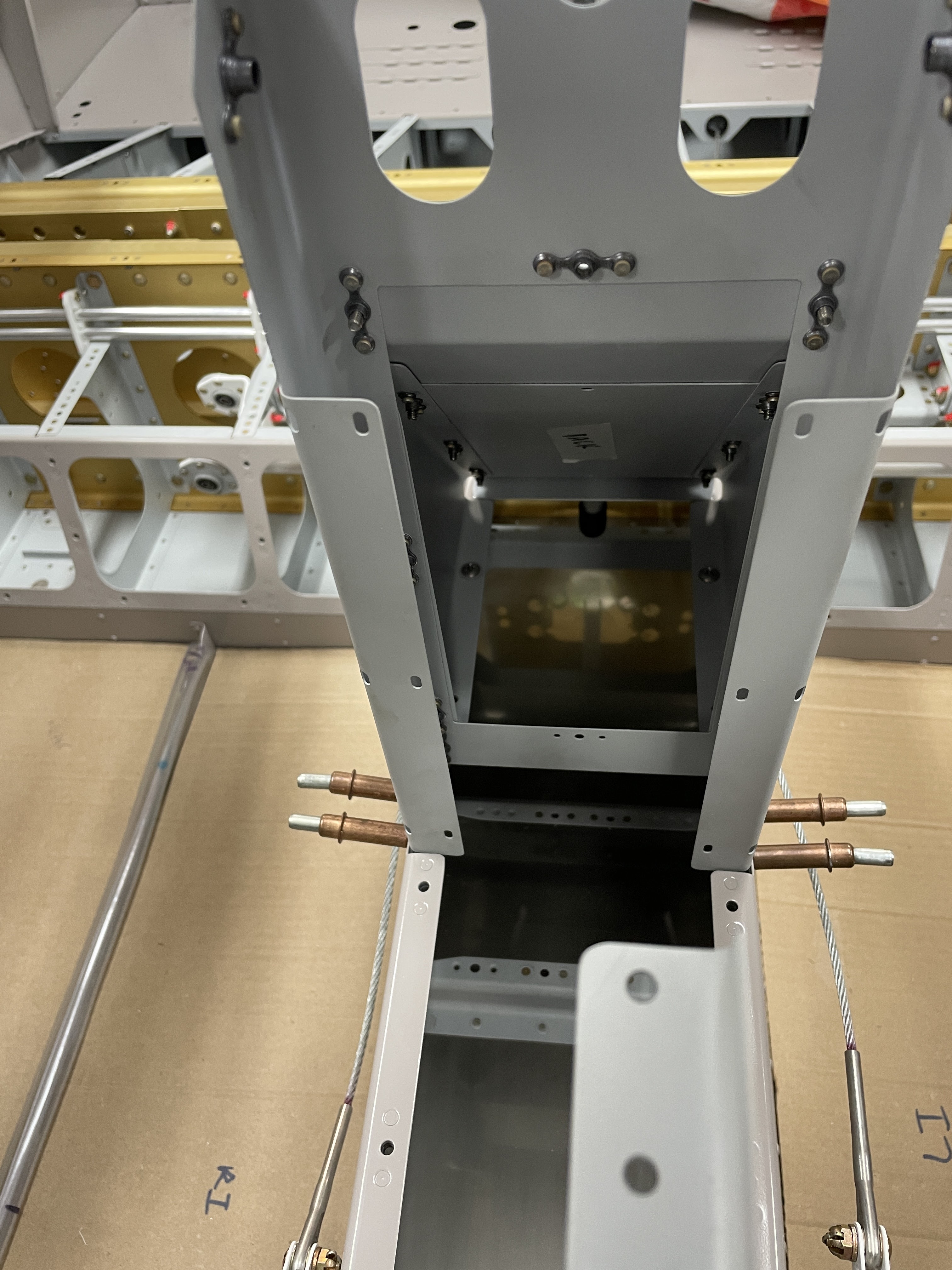
 |
| This is the view behind the wiring channel where the circuit breakers will likely be located. |
The panel parts were removed from the aeroplane and set aside for painting in cockpit color paint - but it's too cold to paint at the moment, so i have to wait until the weather warms up a bit.


No comments:
Post a Comment