Elevator Pushrods & Control Stick Pushrod
To make up the pushrods, i deburred all the parts then used some 3D printed pushrod drill guides, which my dad printed on his resin printer, to match drill the rivet holes. Each pushrod was primed, then riveted together.
The 3D printed guides are great and were downloaded for free from Mountain Ride Aviation!
 |
| I double checked the idler bars cleared the flanges - this was done when the flanges were first prepped for installation, but i double checked again. |
 |
| The stick link pushrod was cleaned and scuffed. |
 |
| These are the Mountain Ride Aviation drill jigs |
 |
| These are such a simple and great idea. |
 |
| I marked the shoulder of the end caps to make sure the end cap was in evenly, before drilling the first hole. I then drilled the hole opposite making sure the marks were even with the end of the pushrod tube. |
 |
| Too large for the booth. |
The end caps were riveted on using pull rivets, then they were hung in the paint booth and painted satin white to match the remainder of the elevator control powdercoated parts.
Once the pushrods were dry, i used some wooden blocks with bolt holes drilled in them and screwed to the bench to set the correct pushrod lengths as per the plans.
 |
| The nail was there to hold the end of the tape measure at the location of the centreline of the bolt. |
 |
| I could then accurately measure where the other block needed to go, and screw it in place. |
 |
| I was then able to adjust the rod ends evenly to achieve the correct length and also the correct rod end orientation. |
 |
| Once at the correct length, the jam nuts were tightened and torque sealed. |
 |
| To tighten the jam nuts on the larger tubes, i used some vice grips and some padding to hold them in place... |
 |
| ... and a carefully placed washer to make sure the whole pushrod remained co-planar during the tightening of the second rod end. It's easy to accidentally rotate the assembly when tightening the jam nut on the opposite end - then the rod ends are not parallel to each other. |
 |
| Both ends are co-planar. |
 |
| The plans length was cross-checked, then torque seal applied to the jam nut. |
 |
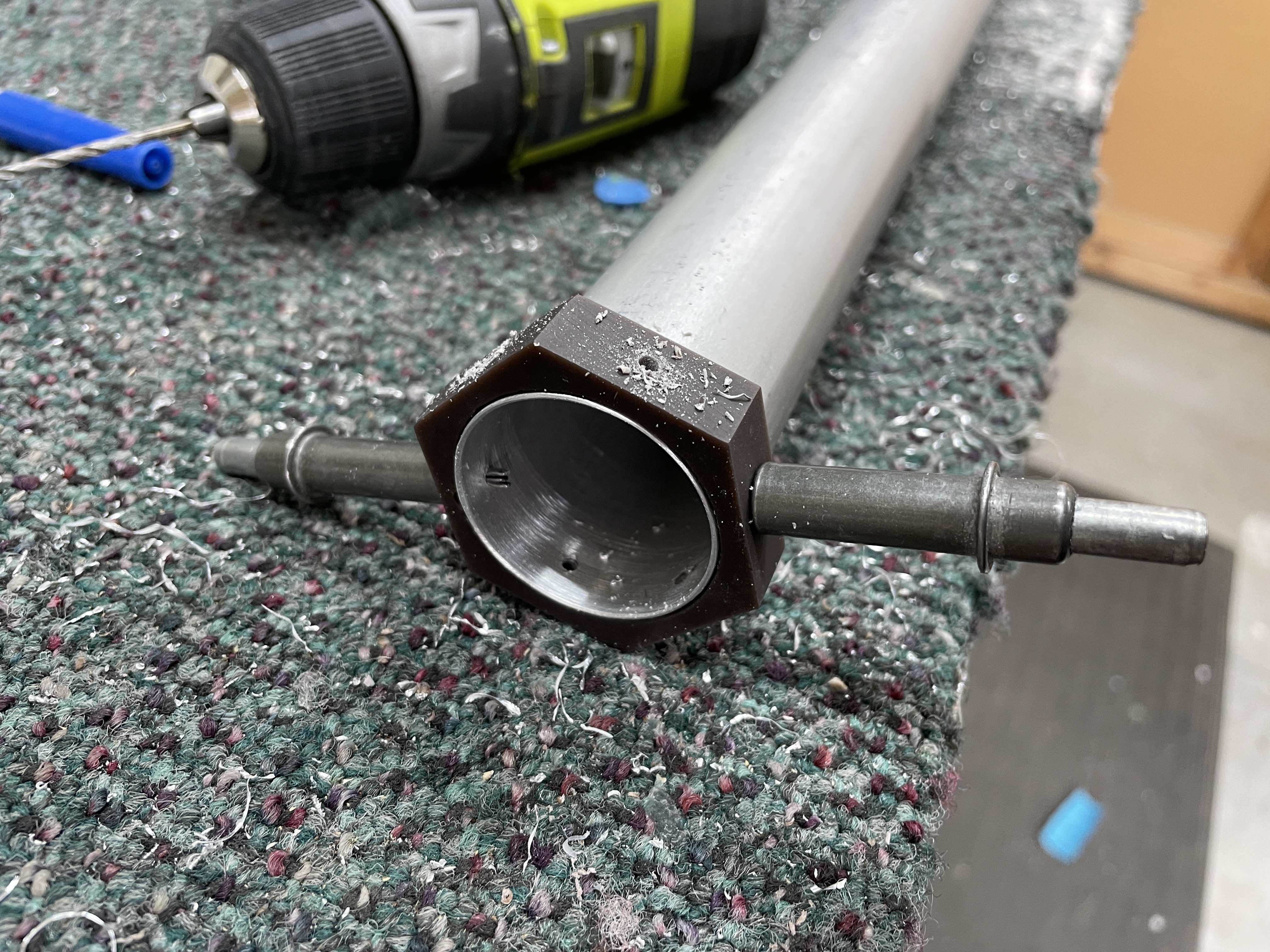
| The 3 tubular elevator pushrod tubes, along with the hexagonal solid stick pushrod. |
Elevator Bellcrank & Mount
The elevator bellcrank parts were prepped, deburred and primed, riveted together then painted satin white along with the idler arms. The idler arms were installed. The elevator bellcrank mount was prepped and primed and nutplates installed.
 |
| Painted satin white to match the rest of the powdercoated controls system parts |
 |
| Nutplates installed |
Control Stick Bases / Drilling the Control Sticks
The control stick bases needed to be installed before installing any of the pushrods, but before than can happen i needed to match drill the sticks to the bases. The sticks i am using are the Tosten CS8 pre-wired sticks, so this was done with the grips installed, as i didn't want to have to fish the wires back down the sticks. However, as it turns out, i didn't like how the wires were just exiting a bare edged hole in the steel, so removed the grips anyway at a later time. If i were doing this again, i would have just removed the grips for drilling. For anyone following, the aluminium inserts are match drilled to each stick, so make sure you don't swap them around - the grub screw won't fit.
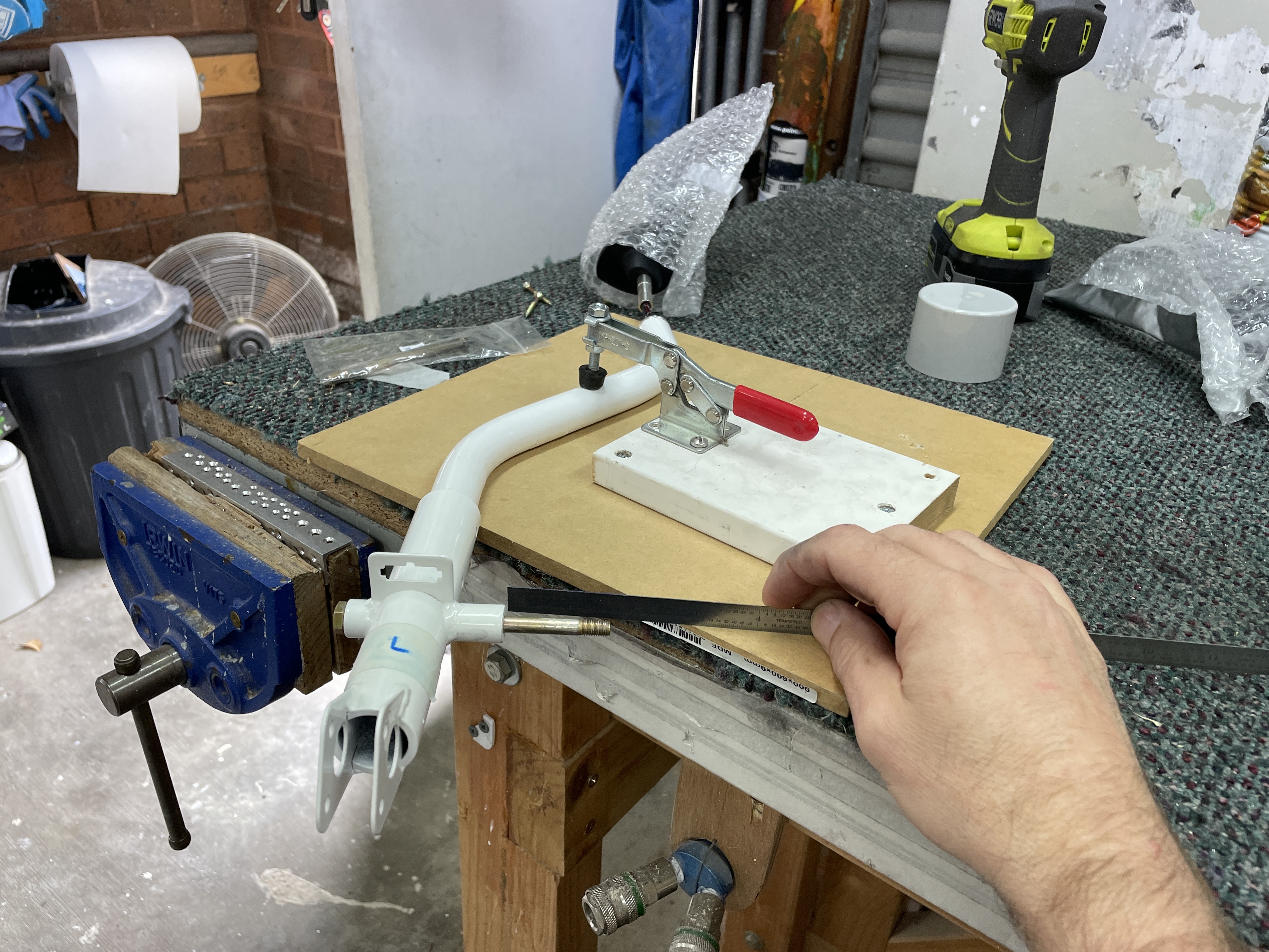
To do the drilling, the grips are clamped to a flat surface, then you are supposed to make the Molex mounting tab parallel to the bench. In my case, this tab was not perfectly aligned with the axis of the bolt - so i aligned the bolt with the work surface instead for the drilling. I used waaaaaay too much super glue and ended up having a hell of a time getting the bases separated from the sticks.
 |
| This was the setup - the stick was clamped to the bench using an over-centre clamp i had in the shed. |
 |
| I used the long mounting bolt to align the stick bases, then superglued them in place. |
 |
| Aligned nicely |
 |
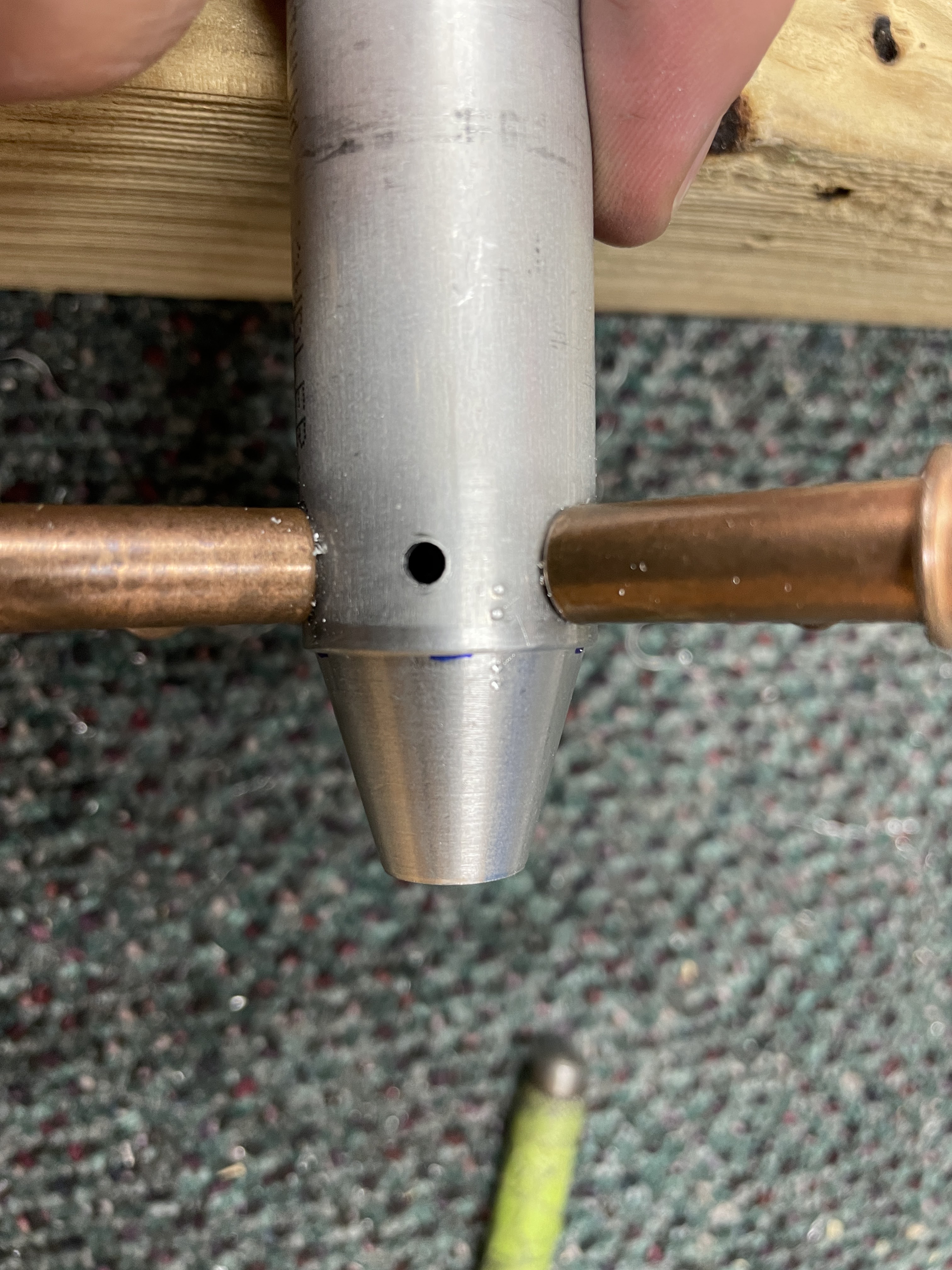
| The sticks were then drilled progressively using a #19, then reamed to 3/16" (instead of using a #12). |
 |
| I had to clamp the sticks and use a big punch and twist the bases off - too much superglue! |
 |
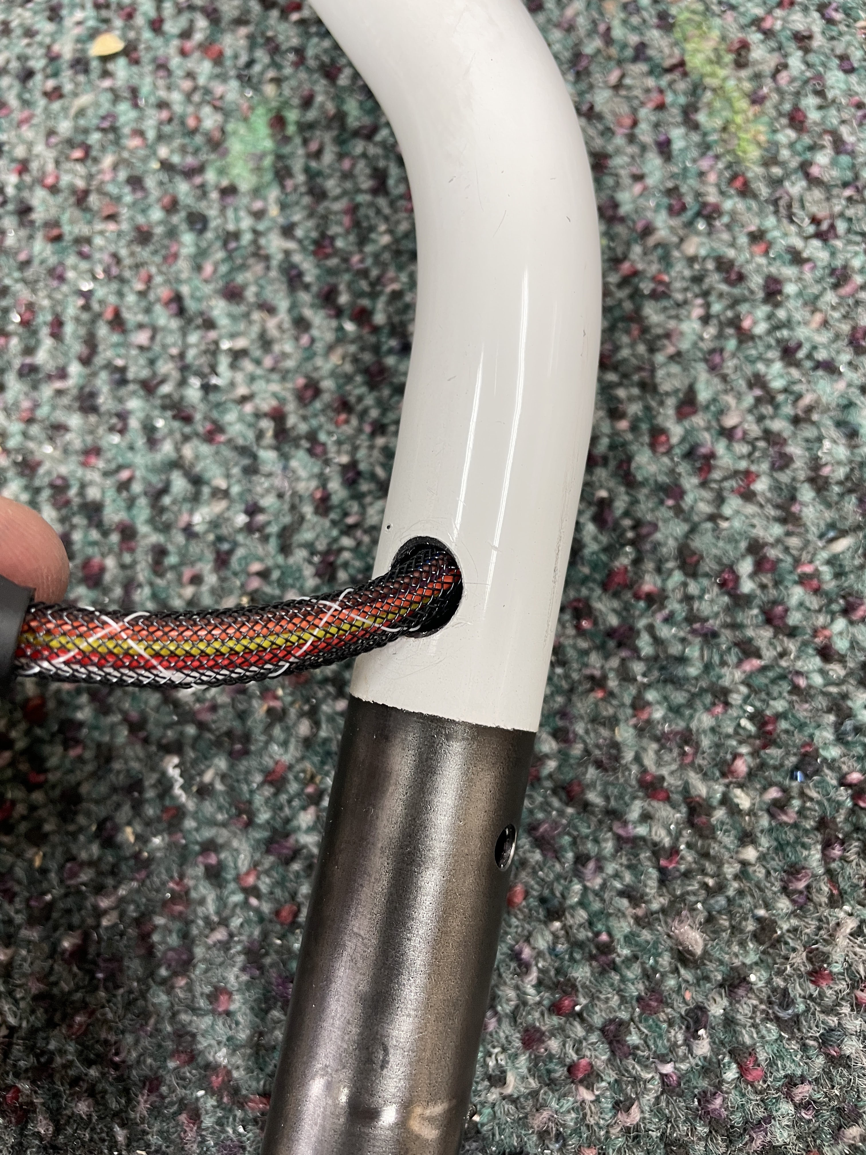
| This was the bare hole for the wires to exit from... |
 |
| ... so i added a grommet into the hole instead. |
Control Stick Bases / Stick Pushrod Installation
The control stick bases were installed first. The stick pushrod was installed between the bottom of the sticks, with a nut installed on only one end (as this needs to be adjusted). Of course, i had to get some glory shots of the sticks in place!
 |
| The large steel capture washers for the outsides of the bearings were scuffed and cleaned up, then soaked in T-9 to help prevent them rusting. |
 |
| As always some PTFE on the bolts to help prevent corrosion. |
 |
| The washer wrenches were not exactly the right size for the weirdly sized 5702-75-60 washers, but a cable tie allowed me to hold them for insertion |
I used a piece of camcord to hold the sticks in a vertical position for measuring, then adjusted the stick pushrod so the sticks were parallel, then installed the final hardware on the remaining side.
 |
| Since the fuselage was tiled over for access, a piece of camcord held the sticks in a vertical position for measuring. |
 |
| Initial measurement at the stick base was 527mm... |
 |
| ... and 531mm at the stick top. So the stick pushrod needed to be lengthened. |
 |
| Final measurement was 523mm at the stick base.. |
 |
| ... and 525 at the stick top. This was as close as i could get it. |
Elevator Pushrod Installation
The idler arms were installed with the final hardware, and the elevator pushrods could then be installed in order.
 |
| The forward most pushrod gets installed from the tailcone, then snaked through all the holes into position |
 |
| It was a tight fit into the powdercoated arm - the ball kept rotating as i tried to push it in. |
 |
| The solution was to use a long bolt in the eyelet ball, which meant i could push it in straight - until the shoulders just grabbed. Then the bolt could be removed and the eyelet slid in fine. |
 |
| I used a mirror to align the rod end ball. |
 |
| Tapping the bolts in was super fun! |
 |
| Likewise, doing up the nut meant being very creating with tools to get onto the nut. |
 |
| I could not imagine how much harder this would have all been without a rotisserie! |
Next up i attached the centre pushrod to the bellcrank, then installed the bellcrank to the bellcrank ribs. I also installed the autopilot pitch servo bracket at this time. Since the bolts were being installed into nutplates, i measured the running torque to ensure the correct torque value was used.
 |
| The nutplates actually had quite a low running torque |
The 2 middle pushrods had their hardware installed at the idler arms.
The last step was to install the aft (the longest) pushrod. I installed this onto the bellcrank, then torqued the bolt (and applied torque seal). This was in error - i should have just left this with a loose bolt - as this pushrod needed to be adjusted later. More on that in a future post!
 |
| Fwd pushrod connection to the stick assembly. |
 |
| A look between the 2 spars. |
 |
| Idler arms where the forward and middle pushrods meet |
 |
| Aft pushrod and bellcrank. |
Of course, i had to pop the sticks in and pretend i was flying!


No comments:
Post a Comment