I have never made up a fuel line before - so it was time to learn 2 new skills: fuel line bending, and fuel line flaring.
I made a
VAF Forum post seeking some help on how to get started, and got a good recommendation to use some wire covered in a PVC tube (close to the size of the fuel line), to template the fuel lines needed. In addition, i did a lot of online research to see what others had done.
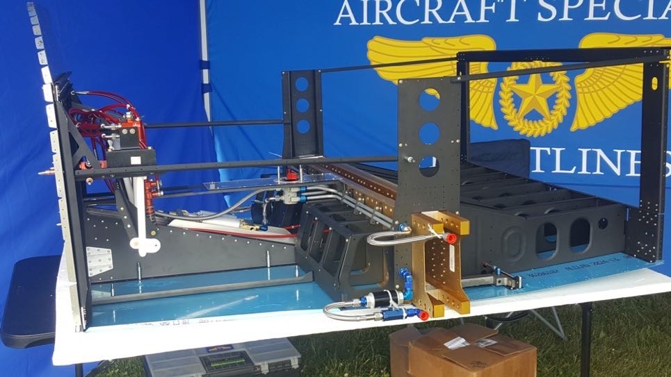
One of the best things i found was actually a photo from the TS Flitelines Duplex Fuel Valve RV-14 mock-up at Oshkosh.
This showed that the fuel supply line would run through the lower hole in the fuel line clips, and was aligned horizontally with the lower fitting of the fuel valve - all this needed was a simple 90 degree bend going through the tunnel sides, and another perpendicular 90 degree bend to drop down to the location where the fuel supply bulkhead fitting was location.
The fuel return lines are a straight run to the bulkhead fitting on the wing side, but at the tunnel opening would need to angle up, before being bend parallel to allow the fuel line to sit normal to the fuel valve flare.
Templating out the Fuel Lines
I had initially thought that i would make up the templates, which would accurately show me what the fuel lines needed to look like, then just bend the tubes to match the templates. As it turns out, the templates are not that useful. I made up one for the fuel supply line, and copied this, but i ended up making the fuel supply line 3 times - the second time was because the template was not accurate, and the third time was due to a brain fart when flaring the end!
The templates may have some value, in some complex fuel line cases, but i think you would have a better go at it with just measuring. In fact, i did not template the fuel return line - i just worked it out on paper and bent to the drawing and it was spot on.
 |
| The fuel line templates were kind of helpful, but not really. |
To work out what the tubing length loss was due to the flare, i made up a test piece of a known length, and worked out that the tube shrinks by 1mm due to the flare being made. The flare fitting dimensions are such that you need about a 2mm flare made on the end of the tube - so if you cut the tube 3mm longer than the dimension from the END of the flare fitting, it works out perfect.
As i worked on this tube, i wrote down the dimensions. Each attempt saw me tweak the dimensions until i got it spot on. For anyone following, these are the dimensions you need:
1. Total Length of Cut tube - 606.7mm
2. First 90 degree bend made 106mm from one end of the tube.
3. Second 90 degree bend made at right angles to the first bend, and made 70mm from the end of the tube.
4. When you do this, the 2 bends end up being 513mm between centres.
 |
| Here you can see my fuel supply line tubing dimensions. It took a few goes to get the lengths dialled in. |
Fuel Supply Line
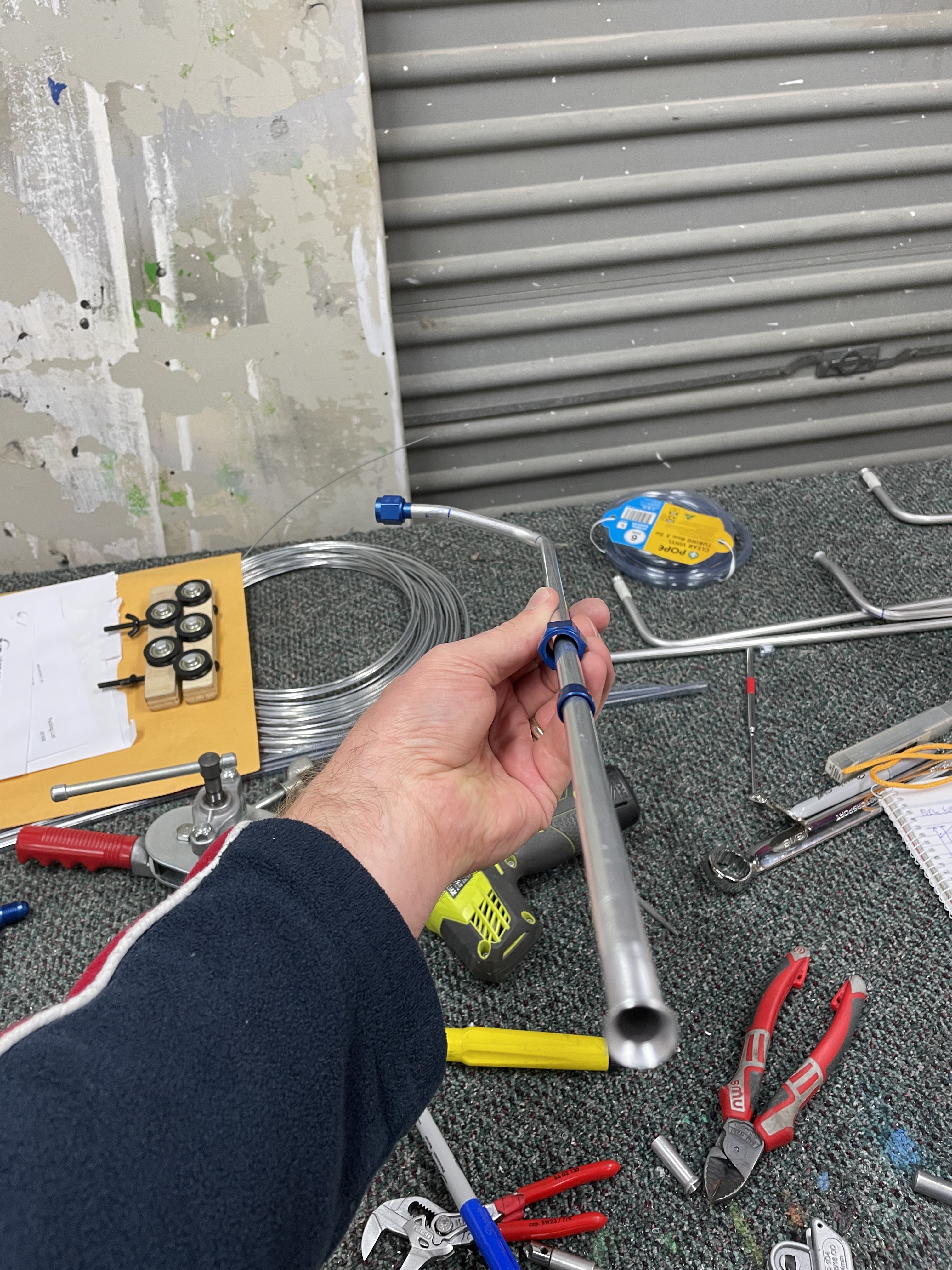
Next up was to flare the ends of the tube. A drop of oil was used on each flare and they all worked well. Just remember to put the sleeve and nut onto the tube before the bend - and in the correct order!!! I had one line which had to be totally scrapped, as i put the sleeve on before the nut.
 |
| The Rolo-Flare tool ready to go. |
 |
| DOH!!! Don't do this. |
 |
| And it fit so well too... this whole line was scrapped. |
The finished line.
Fuel Return Line
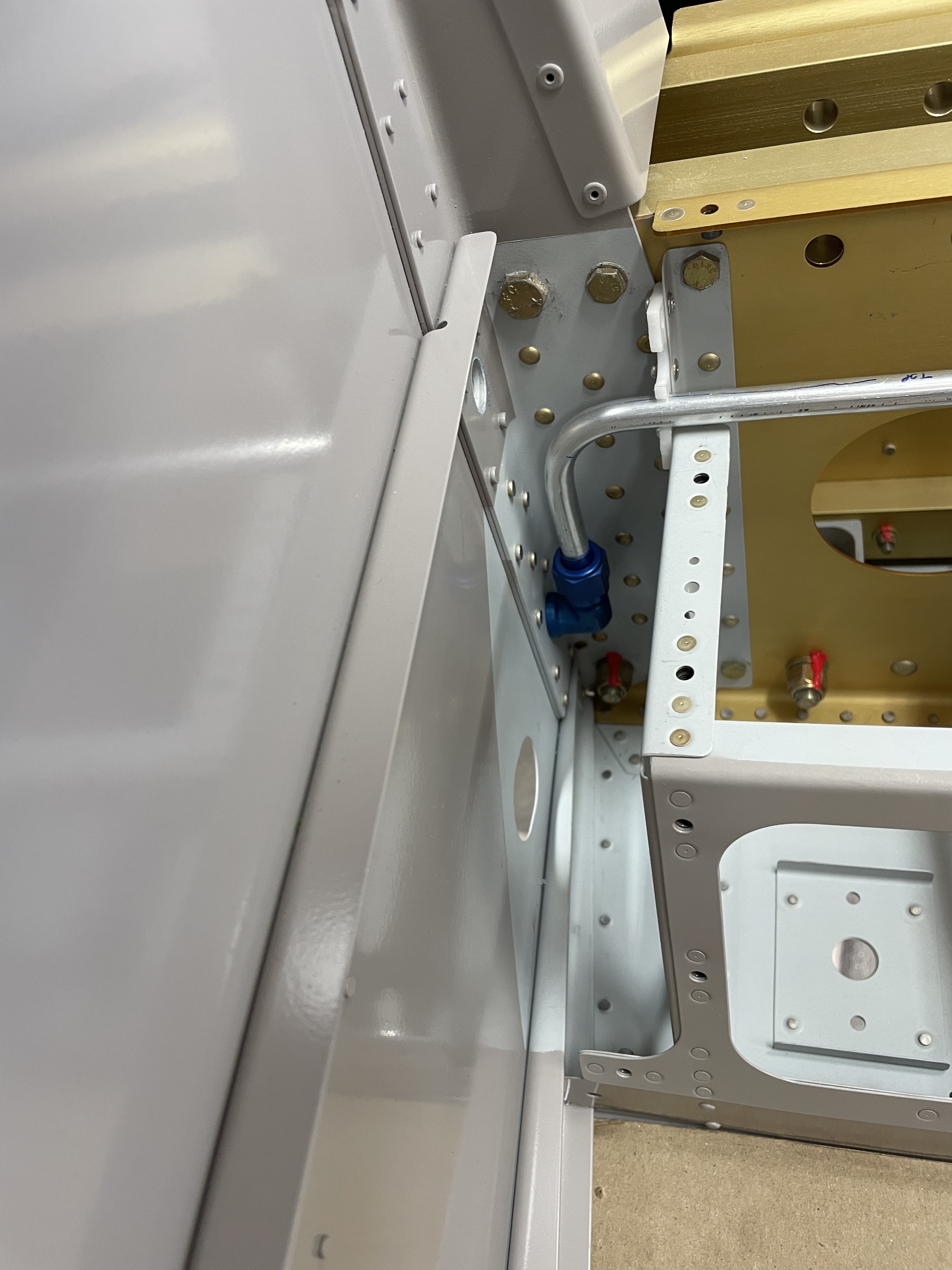
The RV-14 kit comes with a hole already present in the substructure of the side skins for a fuel return line bulkhead fitting. There is a large hole in one substructure piece, then a small #40 hole in the next piece, but the skin is undrilled. I drilled the skin to #40 through the pilot hole, then from the outside opened them up to fit an AN 90 degree bulkhead fitting. These will not be tightened until the fuel lines are in place. The holes were spot primed.
 |
| The pilot hole present is **almost** inline with the upper holes of the fuel line brackets. It was likely aligned with the 1/4" holes that were stock. |
The fuel return line was made in almost the same manner as the fuel supply line. However, instead of using the template method, i worked it out using measurements. I knew the lower hole in the fuel brackets, and the lower fuel valve fitting were in the same plane. I knew the distance between the upper the lower holes in the fuel line brackets, and i knew the distance between the 2 flare fittings on the fuel valve. I also knew that 106mm was the correct horizontal distance between the centreline of the fuel supply line and the fuel supply flare fitting on the valve, so this horizontal distance would be the same for the top fuel line bracket.
So knowing all that, i drew up a scale drawing. I used a 1.5" straight section into the flare fitting on the fuel valve, to give enough space to add the sleeve and nut and flare the tube. This was also the minimum distance to get a bend happening on the tool due to the distance from the bending dies to the tube support arm. When making 2 bends line this, you need to measure and mark BOTH the bends before bending the first one - if you forget, then you have to try and accurately measure the second bend position around a curved tube - easier to mark both of them before the first bend.
For those playing at home, the fuel return line needs to be as follows:
1. Cut overall to a length of 601mm.
2. a 16 degree bend, 41mm from the end of the tube
3. a 90 degree bend, 109 mm from the end of the tube.
4. A straight flare on the other end.
To make sure these were correct, i got a piece of scrap and did a test bend. The end was flared so it could be installed onto the fuel valve.
 |
| The first 16 degree bend. This was made to approx. the 22 degree position to allow for tube spring-back - i then checked it against my scale drawing. |
 |
| Test piece installed - my calculations were spot on! |
The original 109mm mark was still on the 90 degree portion of the tube, so I was then able to measure from the bulkhead fitting and place a mark at the end of the ruler (300mm) then measure from the mark to the bend reference mark. Adding it all up gave me the overall length of the tube needed.
 |
| I measured from the flare fitting and marked a 300mm position on the test piece. (with a 3mm allowance for the flare). |
 |
| I then worked back from the 109mm mark to get an overall tube length needed of 601mm. |
Once i had this measurement, it was a "simple" task of cutting a tube to 601mm, deburring both ends and placing the bends on one end as outlined above. They were then flared on both ends and test installed, along with the fuel supply line.
 |
| The 41mm (1.5") measurement is *just* enough room to get the sleeve and nut on, and still make a flare. |
 |
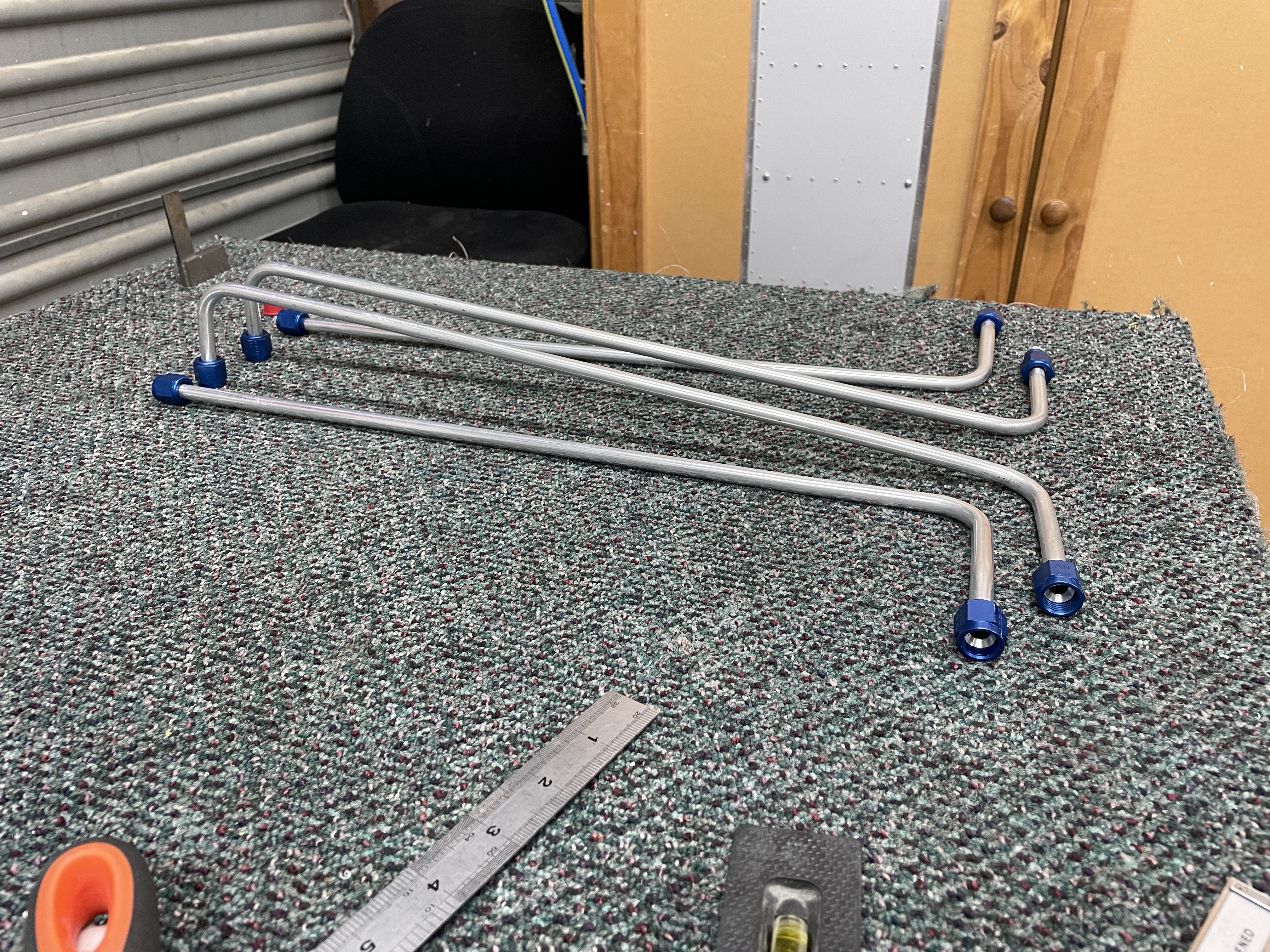
| The finished fuel return line. |
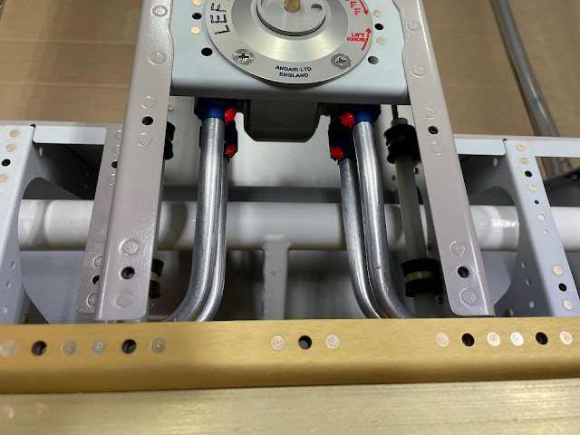
 |
| Fuel return is on the top / Fuel supply on the bottom |
 |
| I'm glad i did this myself - cost nothing more than what parts came in the kit. |
Fuel Valve Fittings
To finalise the installation, the fuel valve fittings were installed and the screws stagged. This is basically using a centre punch to deform the head of the screw, to make sure it can't unscrew itself.
 |
| Fuel valve fitting screws stagged |
Final Installation
For final installation, each line was flushed out with ISO then blown out with air. The lines were installed and torqued up, then marked with torque seal. Once the lines were tightened on to the bulkhead fittings, i was able to tighten up the nuts on the bulkhead fittings themselves.
One last little but very time consuming job was to install the second half of each plastic fuel tank bracket.
 |
| Each nut was also marked with torque seal. |


No comments:
Post a Comment