At this early stage of the build, i am finding i need to make some decisions - without having ordered an engine. One decision, was the type of fuel selector i would need. I am fairly certain i want to have a EFII engine (electronic fuel injection and ignition), meaning i will need a duplex fuel selector - aka, one which allows the return of fuel from the fuel rail back to the tank from whence it came.
The only real options were the Newton V10 valve and the Andair FS2020 valve. The Newton is on permanent backorder, and when i emailed them they basically told me to forget it. They were unable to manufacture new ones due to supply issues. So that left the Andair FS2020. I ordered this on the 8th of June 2023, and finally received it on the 3rd of April 2024 - almost 10 months! You can make a baby quicker than that...
It is a nice valve though!
Installing the Duplex Valve
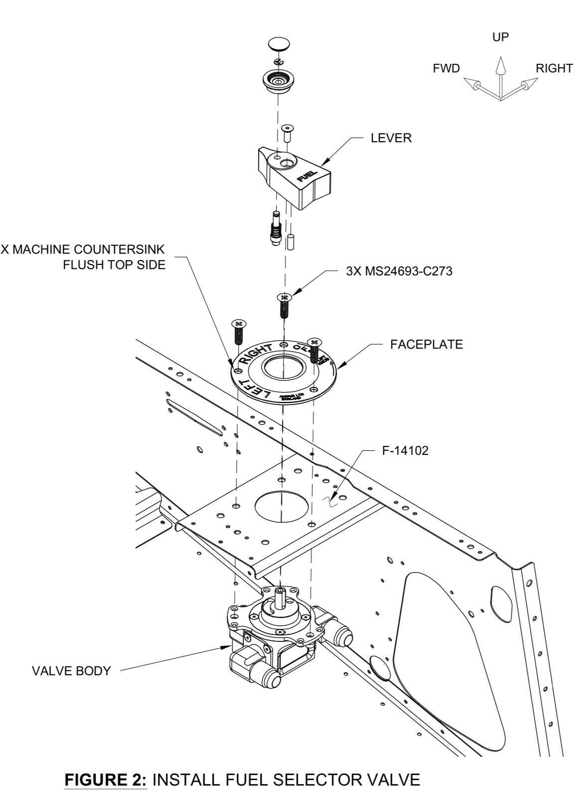
The -14 comes with the FS-14102 plate installed into the top of the tunnel sides, which is designed to take the normal (non-duplex) Andair FS20 Type 2 valve (L/R/OFF). This is designed to have nutplates attached to the valve itself and screws in with 3 screws (two forward, and one aft). The FS2020 duplex valve however, has 4 mounting holes - with no capacity to attach nutplates to the fuel valve itself. The forward 2 mounting holes, also don't align with the original forward 2 mounting holes - they are out by about half a hole. The aft holes fall on a part of the plate where i can match drill some new holes.
 |
| The yellow marked holes are the original holes for mounting the fuel valve, while the green holes are for the rivet tails to poke through, when you rivet on the support ring to the cover plate (clever!). |
 |
| This is how the original fuel valve was mounted - with 3 screws into nutplates attached to the fuel selector itself. |
 |
| The FS2020 Duplex valve is mounted using a 4 hole pattern - with no ability to attach nutplates. |
 |
| Here you can see how the forward 2 holes don't align with the original forward holes of the stock (non-duplex) fuel valve. They overlap by about half a hole. |
 |
| The forward 2 holes don't align. |
 |
| The aft 2 holes land in a good position on the stock mounting plate. |
The new valve does not have a a facility for attaching nutplates, and i was hesitant to use nuts and screws due to the tight location. So, i decided to match drill the valve to a piece of 0.025" sheet, and create a nutplate ring. This will act to clamp the valve into position and i can use the ring to match drill the valve mounting plate already installed into the airframe.
 |
| The good old MathOMat from Year 12 comes to the rescue once again! |
 |
The valve came with #8 countersunk screws, but the faceplate had been countersunk for #10 and the holes in the valve were for #10. So i match drilled for #10. I used #10 screws and nuts as i drilled each hole.
|
 |
| These are the #8 screws which came with the valve - clearly not the right ones. |
 |
| So i used #10 screws (and deepened and tidied up the countersinks a little as well for a nice fit). |
I used the nutplate ring template to centre the valve hole onto the fuel valve plate in the aircraft. I was then able to match drill the aft two holes into the fuel selector plate. As the front two holes were half aligned with the existing holes, these will just be slotted. The valve will be clamped firmly by virtue of the nutplate ring, and will be prevented from rotating (most important) by the aft 2 screws.
 |
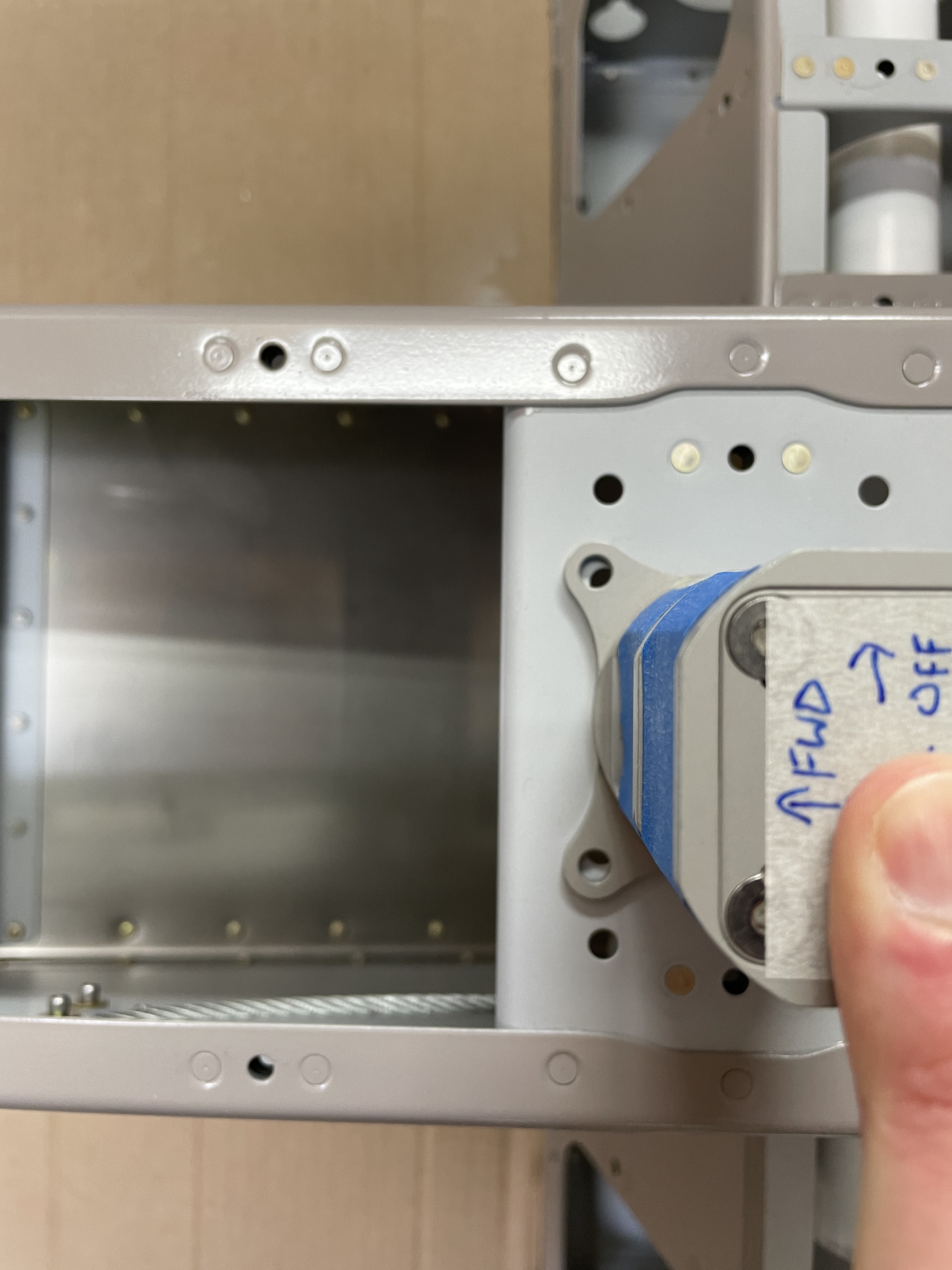
| Here you can see how the valve will fit - the aft 2 holes will be match drilled, preventing the valve from rotating. The existing forward 2 holes will be slotted to fit. |
 |
| I used a MS21047L3 (K1000-3), and an AN3 bolt to make up a nutplate jig, as a #10 screw is the same size as a AN3 bolt (10-32 thread). The #10 screws being used are stainless MS24693-C273 |
 |
| The nutplate jig was used to drill the nutplate attach holes |
 |
| Then i marked a surrounding line, which was a tangent to the edge distance requirements for the #10 and #40 holes.. |
 |
| Once it was trimmed, i centred the nutplate ring and made sure it would fit inside the fuel selector mounting plate flanges. I made sure to have the forward 2 holes symmetrical to ensure the fuel valve doesn't end up crooked! |
 |
| Then match drilled using a #10, and bolting in place as i went. I used the forward holes to file the existing holes into a slot. |
 |
| The forward 2 holes were then slotted forward and outboard to allow the valve to fit. |
 |
| The part was primed and the nutplates riveted on. I was able to use AN470 (dome head) rivets here, as they cleared the 'ears' of the fuel valve and were a lower height than the thickness of the valve flange. |
 |
| The valve ring will sit like this under the valve, and i will be able to screw the valve into place without having to worry about nuts and washers in the difficult to access location. |
 |
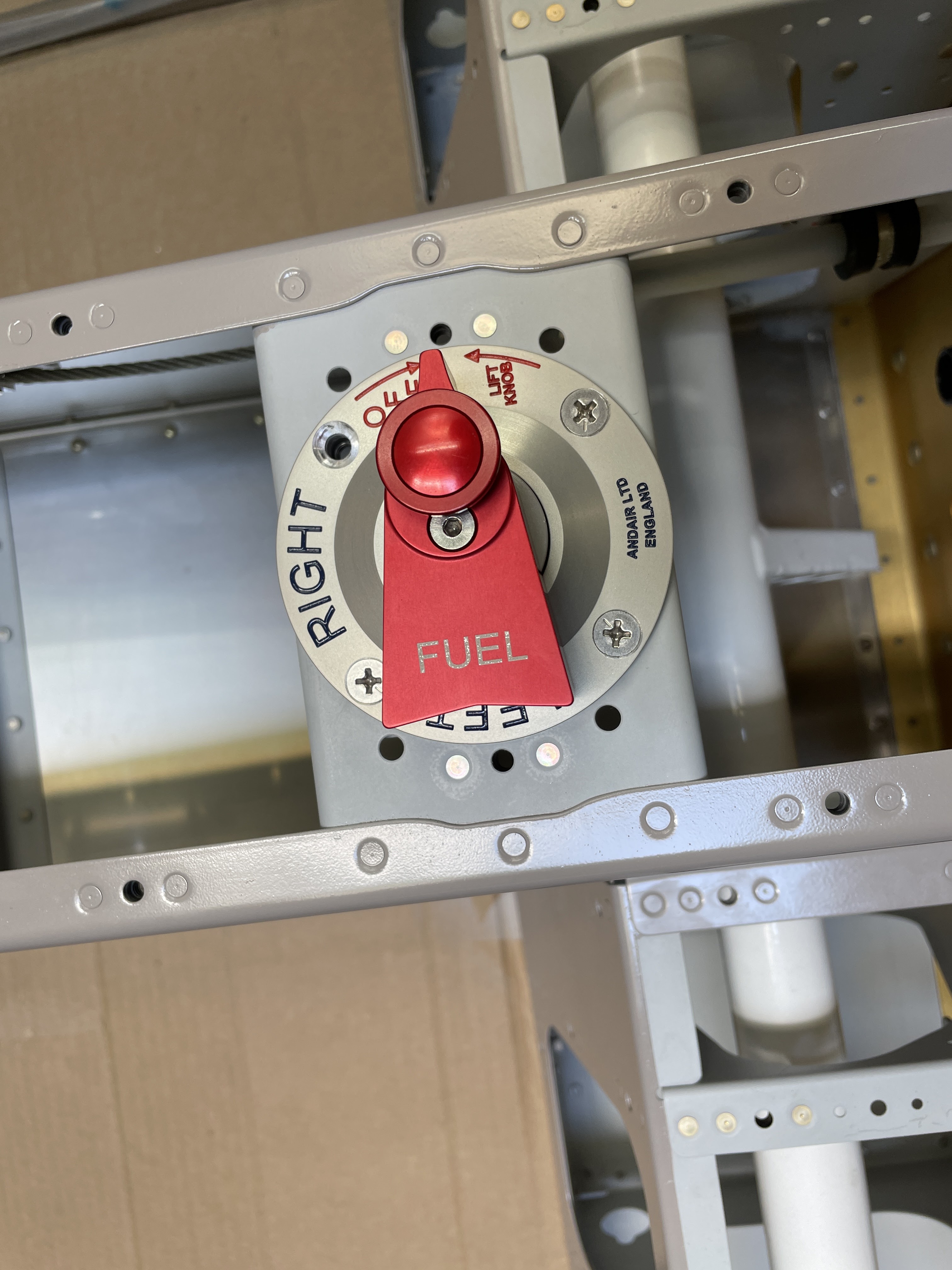
| Here the valve is installed into position - i needed to order one more screw! |
 |
| The nutplate ring clamps the valve to the mounting plate, acting in the exact same manner as nuts. It is just **a lot** easier to install the valve with this in place. |
 |
| Here you can see how the ring fits nicely above the valve fittings. I need to decide exactly what fittings to use on the valve, then screw and stake them in place, before installing the valve proper. I can then make the fuel lines. |
Fuel Line Mounting Brackets
The fuel lines are held to the under-seat area forward of the spar using some nylon 2 part brackets. The lower hole in each bracket is sized for a 3/8" fuel line, but for some reason the upper hole is sized for a 1/4" fuel line. Since the EFII systems uses the same sized fuel return as supply (both 3/8"), i need to upsize the upper hole in each bracket.
This was done initially by jigging each fuel line bracket onto a piece of timber using some #10 screws, and a 1/4" pilot hole into the timber to take the 1/4" end of my larger step drill. The holes in the brackets are sized for a #10, however the plans call for the use of #8 screws - i assume to give some play to the brackets when installing the fuel lines. Drilling got me through the upper bracket to 3/8", then i moved the fuel line brackets over to a new position on the wood with a larger (5/16") hole, so i could drill the lower bracket also to 3/8".
 |
| The smaller hole in the fuel line brackets was already 1/4", so i match drilled the #10 screw holes to hold the brackets in position, then match drilled the 1/4" hole into the timber. This gave a spot for the 1/4" end of my larger step drill to ride in, and allowed me to drill the upper bracket (and partially the lower bracket) to 3/8" without the drill wandering off. |
 |
| I then did the same thing, but enlarged the 1/4" pilot hole to 5/16" (holes on the right of the image above), so the next step up on the step drill could act as a pilot for drilling the lower bracket to 3/8" also. |
 |
| Lower holes all drilled to 3/8" |
 |
| Here you can see how the new hole is 3/8", but needs to have the corners filed straight, as well as be filed a little deeper into the bracket to match the depth of the stock 3/8" hole in the brackets. |
To file the holes deeper, i simply filed off the corners using a flat file, then mounted each bracket into a mini-vice and used the vice as a file guide to make sure i did not go too deep. I used an offcut of fuel line to test the fit.
 |
| The blue line is a tangent to the pre-drilled 3/8" holes, and shows how the new holes need to be elongated into the bracket. |
 |
| I used a vice with smooth steel jaws as a filing guide. |
Once the brackets were finished, they were installed with LP4-3 rivets as per the plans. Some were set with the head of the rivet on the bracket and the shop head on the seat ribs. Others were set with the shop head on the bracket, and these used a 4-40 washer as a bearing surface for the pull-rivet to squeeze against, instead of bearing against the nylon. These were all done with my hand riveter, and i used a modified piece of trailing edge rudder angle as a wedge tool - i had to grind one side of it away to fit around the bolts holding the ribs to the forward spar.
 |
| The modified rudder trailing edge wedge, ground down to fit around the bolt heads holding the seat ribs to the spar. |
 |
| 4-40 washers were used as a bearing surface where the shop head of the rivet was against the nylon. |
Next up will be to have a go and making some fuel lines!


No comments:
Post a Comment