As always, the chapter starts with cutting parts apart, and deburring. The little spacers were cut using a plumbers tubing cutter, then finished up on the drill press (aka the poor man's lathe).
I was not sure how i should finish the brake pedals - the obvious (and easiest) choice is to leave them bare aluminium. I could also paint them, but this risks the paint wearing off over time as they are used. So i made a VAF post asking the question! I created a poll to see what other people had done, and had 79 responses:
I emailed a local powder coater, as well as an anodising company. I only got a response from the powder coater, so that's what i decided to do:
 |
| They were finished in a textured black, used on truck beds. |
 |
| I had the steps powder coated white at the same time. |
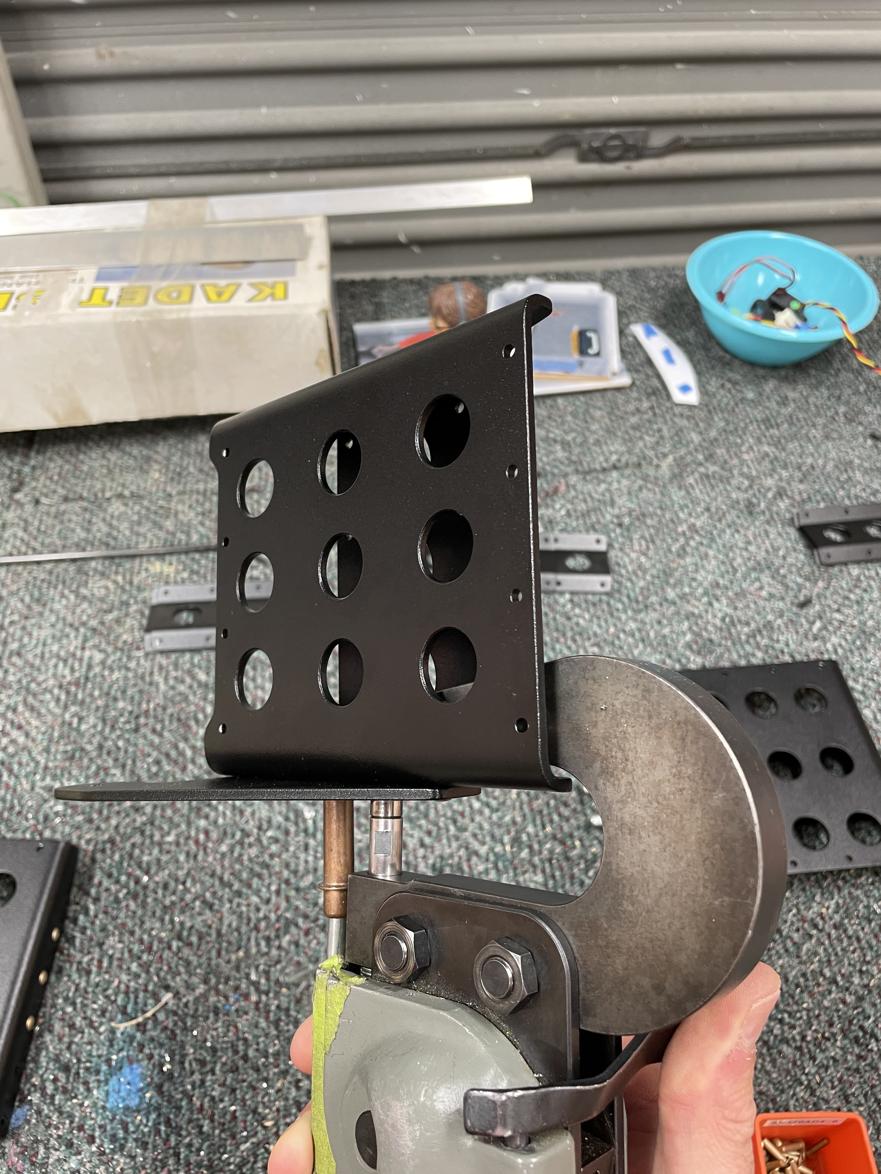
I was then able to rivet them together:
 |
| I was able to reach all the rivets using the squeezer. All the holes had to be reamed again to #30 to remove any powdercoat stopping the rivets going in. |
Assembling the Rudder Pedals
The brake pedals were installed onto the rudder bars as per the plans. I had read in some Van's types, to avoid binding, one long -56 length bolt was used instead of a bolt on each side of the pedal. I was not able to find any build logs for a -14 where someone had done this, so
asked the question on VAF. It seems the -14 is fine with the 2 single bolts, so long as the 'ears' where the pedals mount are parallel to each other. I was not able to get any long AN3-56 bolts locally, and I had already purchased from eBay some 3/16" stainless rod, so i used this rod and a square to align the 'ears' to make sure they were parallel.
 |
| Most of the 'ears' were well off being square / parallel. These were just gently bent back using my hand seamers. |
 |
| Before... |
 |
| After... |
Once the 'ears' had been straightened, i was able to install the pedals using the hardware called out in the plans. I loosely placed the brake pedals into position, and slid them over to one side. I then measured the gap, and chose thick washers first, then thin washers, and in one pedal a 1/16" shim to make sure there was no play side to side. The bolts were installed using grease.
 |
| I was able to divide this measurement to work out how many thick or thin washers could be used to get as close as possible to the measurement. |
 |
| The 'washer wrench' was again, a lifesaver |
 |
| Cotter (split) pins are strangely satisfying once you get the hang of them. |
It was important that the brake pedals did not bind at all - they need to be free so the internal spring in the master cylinder can return the pedal to zero deflection. The master cylinders will bypass fluid pressure to the pedals on the other side of the cockpit, only in the last 1/16" of travel. It is important that the pedals have no resistance in allowing the internal spring to move the pedals back into this position:
Installing the Brake Master Cylinders


No comments:
Post a Comment