The RV-14 kit does not come with a park brake. Back when i ordered the fuselage (when it was permitted to have additions or deletions to your kits), i included the following items into my order, hoping to eventually find a place to include a park brake:
 |
| Matco Parking Brake Valve PV2 |
 |
| 72" Button Lock Bowden Cable CT A-700 |
 |
| HW WIRE NUT KIT |
Basically, the parking brake valve interrupts the normal brake lines from the master cylinders to the firewall, and is mechanically operated. You press on the brake pedals, then close the valve which traps the brake pressure in the lines, holding the brakes on. With this valve, you can actually actuate the valve closed, then apply the brakes and it will allow the pressure to pass through, then hold it.
The question is - where do i mount this valve, and how will it be actuated!
I decided to copy the location which was specified in the TS Flitelines cabin hose package. Their product replaces the plastic brake lines provided by Van's - i would have chosen it if it were not for the price (USD/AUD rates) and the fact i can get -3AN brake components locally here.
 |
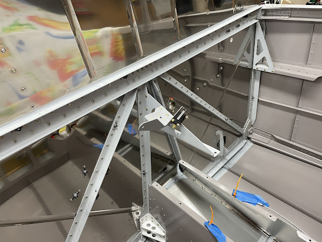
| The park brake valve is mounted to an angled bracket which attaches to the rudder bar support angle off the firewall. This is the perfect location for this, as the hose routing is clean and simple. |
So to get started, i needed to plan out the hose system to make sure that the valve would be in a location which made sense for my aircraft. You can see below the parts i will need to order to end up with a kit basically the same as the TS Flitelines setup (but roughly half the cost).
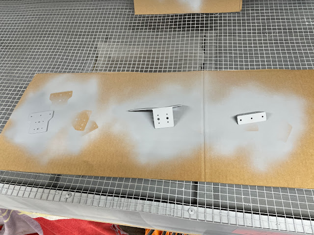
So, to get started on fabricating a bracket. I had some 0.063" thick flap hinge brackets left over - as you get enough to build a set of RV-10 flaps (these have been pretty handy in the build so far). I cut out a bracket shape i thought would work, with the idea of bending these with my vise mounted bending brake. The brackets are 2023-T3, and as it turns out, really didn't want to bend.
To start, i laid out the park brake valve and traced it's side profile - i worked out what angles the arms actuated the valve, then drew up a V1 drawing of the bracket which would hold the bowden cable. I cut this out of the flap bracket, then tried to bend it. But it was just not playing ball - a new plan is needed.
 |
| Tracing the side profile. |
 |
| V1 of the arm shape to hold the bowden cable. |
 |
| 2024-T3 in 0.063" does not want to bend!! |
So back to the drawing board. The next attempt was to build the mounting bracket base from a piece of angle i had left over, and the remaining section of the flap bracket. This had some holes drilled in it already, so i incorporated these into the design.
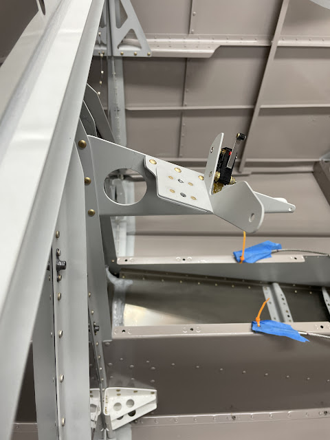
The idea this time is to make up a base plate, which is riveted to an angle to attaching to the airframe. The base plate will have 2 nutplates for the AN3 mounting bolts. On top of the plate is a piece of large angle (cut from a 50mm tube), which will sit under the park brake valve, and have the 'arms' to hold both the bowden cable, and a microswitch (the re-purposed stall warning switch) to give a discrete if i want a 'PARK BRAKE ON' CAS later. The arms will align with the actuating arm of the parking brake valve to give a physical stop at the open/closed position. The 'mounting arms' angle will be riveted to the base plate using the nutplate rivets.
 |
| The base plate clecod to the angle - the 3 #30 holes were already in the flap bracket. |
 |
| The angle will attach the assembly to the centre rudder bar support angle from the firewall. |
 |
| I used some drawings to work out the geometry of the mounting arms. |
 |
| The arm on the left will hold the bowden cable bracket, and the arm on the right will hold the microswitch. |
 |
| Working out the dimensions of the microswitch mounting arm. |
 |
| Since this is not a structural piece (it just holds the arms), it was made from a 50mm square tube from Bunnings Aerospace, which is a 6063-T5 temper. |
 |
| The arms at each side give a mechanical stop at each end of travel. |


No comments:
Post a Comment