Once the bottom skins were riveted together, I went back to the start of Chapter 29 and the next step was to work on the control column assembly. First up, was some match drilling of the VA146 bearings and included a step where one side of the front bearing was trimmed to match the powder coated steel parts - however, the plans only call for this on the LEFT bearing?
I posted a question on the VAF forums, but didn't really get a good answer. However, the answer comes from reading the plans. Referring to page 36-14, it turns out the left control column has 2 bolts (an upper and a lower), while the right column just has the upper bolt. The trimming of the left flange, is to clear the bolt on the left hand column. In any case, i elected to trim BOTH forward bearings.
 |
| The bearings were protected with tape before any drilling, or prep work was done. |
Once the bearings were prepared, they were primed along with the longerons and other parts up to this point.
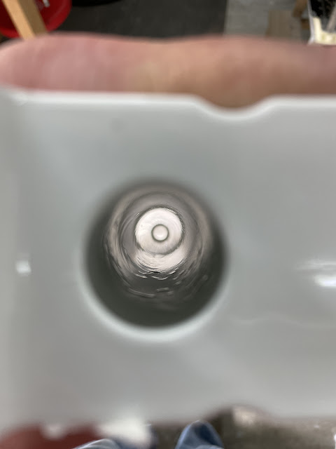
Next up i did some work on the control column assembly itself, including clearing out the powercoat in the bearing holes using a step drill, as well as final drilling the bolt holes. I also primed the inside of the control column assembly using the ShipShape primer (the EkoPoxy primer is not suitable for steel). I cleaned off any surface rust etc using a scotchbrite pad on the end of my 'pick up' tool, then cleaned everything out with acetone.
 |
| Good primer coverage inside the tube. |
Binding Issues - how many washers and shims?
There have been a few RV14 builders who have experienced binding of their control column assemblies in the pitch axis - the understanding is that this is due to side loading on the bearings when the bolts are tightened due to an incorrect stack up of washers / shims. A good discussion on this can be found here.
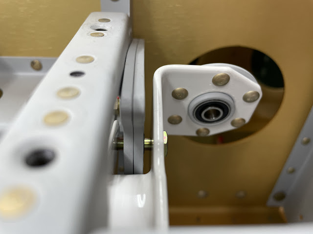
To try and avoid this situation, i decided to measure the gaps between the 'arms' on the control column, then subtract the measurement across the bearing. This gave me an overall amount which needed to be taken up with washers and shims. An image of the gaps which need to be filled can be seen below:
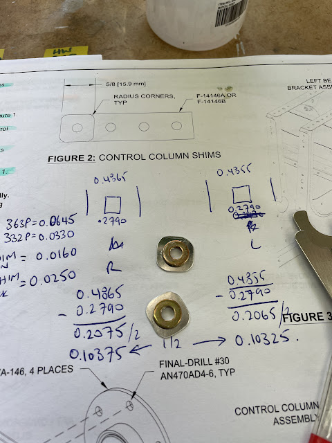
To work out what hardware i needed, i decided to break out the maths:
An explanation of all this can be seen below:
Once i had figured this out, I installed the control column assemblies using this hardware, and used temporary nuts to see if it was right! I just cut the thinned shim material in half to make the temporary shims easier to install. I used my washer spanners to make the job easy.
 |
| These washer spanners are invaluable! |
And... it was smooth and free!
And of course - i couldn't help myself!
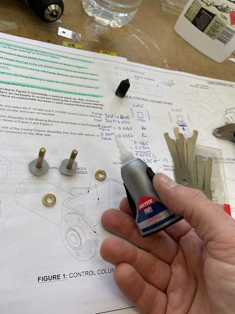
Now i knew which shims were correct, i removed everything and trimmed, deburred, cleaned, etched and primed the shims. After painting the shims them ended up 0.001" thicker - no way that will cause a problem. To make the smaller shims easier to install, i superglued them to their adjacent washer.
 |
| The shims ended up being 0.001 thicker due to the primer. Shouldn't affect anything right? 2 thou more total! That's nothing! |
Once the hardware was installed again, i torqued up the nuts to make sure the assembly was still smooth and free - but remember that extra 0.002" due to the primer on the shims? Turns out, the additional thickness of the paint on the shims caused some binding!!
So, i made up 2 more shims (this time with no primer) and reinstalled everything again.
This did the trick - a free and smooth control column assembly. I ended up using 3 thick washers and one thin shim for each side of the control column as seen in the photos above.
Time to rivet some longerons!

.png)


No comments:
Post a Comment