Once all the primer was dry, i began to rivet the HS rear spar together. I initially clecod the rear spar doubler to the rear spar, and realised i had clecod it on with the wrong face to the spar - it was almost symmetrical, however the rivets fit into the holes much better when i realised and flipped it over.
The rear spar doubler has a couple of AN426 countersunk rivets in the rear spar where the elevator bracket assembly bolts. I decided to back rivet these using my normal tungsten bucking bar, taped into place.
 |
| Instead of rivet tape, i use removable 3M tape |
Once these were done, i used the cupped set and the tungsten bucking bar to finish all the other spar doubler rivets. There was only one rivet that needed drilling out, and i inadvertently put the shop head on the rear face (which didn't look great).
 |
| For AD4 rivets, i like to drill the head off with a #31 drill bit, then once it is snapped off, i use the #41 drill to drill out the centre of the rivet shank. They tend to just pop out then. |
Once the doubler was riveted on, i riveted on the elevator brackets.
The final task on the rear spar was to bolt on the centre elevator bearing bracket. This involved torquing the MS21042-3 all metal lock nuts onto the AN3 bolts. This required measuring the "prevailing torque" of a new nut onto a new bolt. To do this i used a beam type torque wrench, and held the bolt head in a drill press vice, that was clamped to the work table. I used a normal ratchet to screw on the nut so that one thread was showing through the nut. I then got the nut running, and read the "prevailing torque" off the wrench. For reference, i also measured the torque from some normal AN365 nylon lock nuts. Below are the results - these values were added to the standard torque values from Van's manual section 5.


I was then able to bolt the elevator bearing bracket onto the rear spar, and torqued the nuts to 38 in/lbs using a calibrated click type beam torque wrench. I used torque seal to visually show the nuts had been torqued. The bolts went into the holes with a little bit of persuasion, so next time i will use a 3/16" or a 1/4" reamer to finish the holes, instead of a #12 or 1/4" drill. I read that i needed to keep the torque seal off the threads, to prevent galling later if removing the bolts, so i did that.

Moving onto the front spar, the first step was a number of countersunk rivets in the doubler, where the VS attach bracket will bolt on later, and also where the HS bolts to the aft fuselage attach bars. I was able to fit my large back riveting plate under the doubler, and i used wooden blocks to hold up the ends of the spar. I had to grind down the plastic end on my back-rivet set so that it nested nicely into the spar caps. When i was doing this, it must have put some sideways pressure on the roll pin that holds the plastic end on, which sheared the pins and the end fell off - need to fix that! I used some wooden shims on the bucking bar when doing the lower rivets, to make sure the bar stayed perpendicular to the rivets.
 |
| Backrivet tape holding the rivets in |
 |
| Modified edge to the end of the backrivet set |
 |
| I use electrical tape on the cupped set as this eliminates all rubbing of the set on the head of the rivet and leaves a nice rivet |
 |
| Shims used on the bucking bar so that it remained perpendicular to the tail of the rivet |
 |
| Shims used on the bucking bar so that it remained perpendicular to the tail of the rivet |
All the rivets turned out very well - i was pleased, except for one where i did not keep the set 90 degrees to the spar and got a little smilie on the paint - it did not go through to the aluminium doubler though - so i think it is just cosmetic.
 |
| A little smilie on the rivet in the centre |
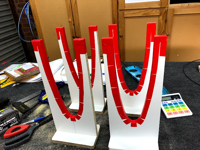
I then moved onto creating the cradles for the HS skins. This was a simple matter of following the plans and i made a cardboard template of the HS nose and inspar ribs - i traced it about 5mm larger as i was planning to use tape and foam weather seal on the cradles.
Next up is a lot of HS rib preparation!


No comments:
Post a Comment