Outboard Aileron Bracket
15-02 starts with preparation of the parts of the outboard aileron brackets.
Inboard aileron brackets as per SB 16-03-28
The inboard aileron brackets were prepped according to SB 16-03-28 dated Mar 11, 2018 - this includes the countersunk holes on the inboard angle bracket (lower 3 holes). The earlier dated versions of this SB used AN470 rivets but there was some interference with the ailerons (apparently). Interestingly, the parts for the original inboard brackets were not supplied with the the kit - only the parts for the SB.
 |
There are a lot of parts in the SB kit - at least in the instructions there are pictures of both the left and right brackets.
|
 |
| The aileron bracket parts after priming |
Rear Spar Doublers
There are 3 x 0.040" thick doublers that nest inside the flanges on the aft face of each spar. One for the outboard flap bracket, and one for each aileron bracket (the inboard flap bracket doesn't have one - probably because of the number of ribs in this area). The plans call for the match drilling of these doublers to the spars - easy peasy lemon squeezy. Such a simple step....
Each one was clamped to the spar, then as i progressed with the match drilling i added clecos. The outboard aileron bracket doublers were aligned with the end of the spars and drilled.
 |
| WOW - what a good job i have done here. |
The inboard aileron and flap doublers had a line drawn on them 5/16" in from the ends, which was aligned with the centre of a row of holes before match drilling.
 |
| The line drawn 5/16" in from the edge of the doubler is aligned with the holes. |
See - easy right! But wait:
 |
| The doubler must be aligned to the end of the spar... |
 |
| To the OUTBOARD end of the spar - where the aileron bracket is! |
OOPS: It turns out that i did not have my head on straight, and i inadvertently drilled the OUTBOARD aileron bracket doubler to the root end of the spar:
 |
| Such nice match drilling.. |
 |
| But it should have been match drilled to this end! |
A lesson learned
The lesson i took away from this is, if i am going to continue to work both the left and right sides of the aircraft at the same time, i really need to mark the orientation of parts AND to understand what the part is for and were it goes. If i had have marked the spar before drilling and understood that this doubler goes under the aileron bracket, i might have avoided this mistake. I have an idea to fix this - more on that later!
Rear Spar Doublers (post headslap)
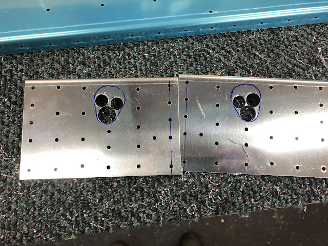
Continuing on the rear spar doublers, i needed to open up the hole in each side where the aileron pushrod will connect to the aileron. This was done with a step drill, dremel/cutting bit/sanding drum bit, and a file.
 |
| This doubler is shocked that i destroyed the outboard doubler. |
 |
| This cutting biy worked very well for removing the bulk of the material.. |
 |
| ..and a sanding drum bit finished it off. |
 |
| Der.. |
Rear Spar Attachment Doublers
After the above doublers were done, i deburred the thick wing spar attachment doublers and drilled the attach hole on the small one to 11/32" using the drill press. Then the whole assembly (minus the outboard aileron bracket doubler of course) was clecod to the wing. The assembly was final reamed to the wing ribs, then removed and the remaining holes were reamed on the bench (where there were no ribs involved). There were 6 holes on ribs 2 & 3 which were match drilled from the attachment form doublers to the ribs. Of note was that i had to increase the width of the spar flange cutouts where they went around the flap brackets by 1/16", because they were rubbing on the flap brackets.
 |
| I checked about 4 times that the attach doublers were not on upside down |
 |
| Only the aileron attach angle brackets (front and back) were attached for final reaming. |
 |
| the gap between the spar flanges was increased by about 1/16" to clear the flap brackets |
 |
| These 6 holes were match drilled to the ribs. |
Countersinking Rear Spar
The plans call for countersinking the flanges of the rear spar where the doublers are located for a skin dimple, so these were done 0.007" deeper than flush. I did this with the doublers in place (and will have to do this to the outboard doubler locations when i fix that little mistake). Similarly, the rear spar attach doublers were countersunk for the head of a rivet for the lower rivet line, and for a skin dimple (the flap gap cover) - again 0.007" deeper than flush.
 |
| The countersinking supervisor. |
 |
| The flanges were countersunk for a skin dimple |
 |
| A coupon was used to check the countersink depth |
 |
On the left is a countersink so that the rivet head is flush, whereas on the right is one 0.007" deeper (for a dimpled skin) Its amazing the scratches etc on and around the hole from the swarf - however there are all removed once scrubbed with a scotchbrite before priming.
|
 |
| The same holes after scotchbrite (the 0.007" deeper than flush is on the left). |


No comments:
Post a Comment