
A smoke system is a fairly simple thing - a tank of smoke oil, a pump, injectors into the exhaust and a switch to turn the pump on! Easy, right?
I have flown a lot of aircraft with different smoke systems - some as simple as above, and others a bit more complicated which include stick mounted switches and reversing pumps (to fill the system via suction).
I had a think about what worked in these systems, and had a couple of design goals:
- The smoke system needs to be activated without having to look for a switch (especially when flying formation aerobatics).
- The smoke system needs some feedback as to whether it is on or off (visual and/or aural)
- The smoke system needs to have the ability to be controlled by a skytyping controller (meaning a solenoid and a diaphragm pump, as opposed to a gear pump).
 |
| Our DR107 One Design makes great smoke - but uses a reversible gear pump, not suitable for Goal 3. |
Goal 1- Stick Mounted Switch
In our DR107 One Design, we incorporated a stick mounted switch. This was an OTTO button which mechanically latched down when it was on. You could press it once and the smoke turned on, and again and it turned off.
In the RV14 however, i have already purchased Tosten CS-8 Sticks. These have only momentary buttons, which all switch to ground. So i needed a system whereby i can activate a 7.5A pump, using a momentary switch and have it stay on until the switch is pushed again.
I looked at a number of 'latching relays' to achieve this, however after a lot of around and around, i worked out that it would not be possible (for a multitude of reasons, but mostly because they needed to switch the power to them, not ground).
Therefore i decided the best course of action was to use a combination of normal relays, combined with an Arduino Microcontroller. An image of the wiring diagram is below.
Goal 2 - Status Feedback
Since i will be using the Arduino, feedback on the status of the system is easy! The Arduino is able to ground pins using programming logic - i have therefore been able to provide output wires which go low to trigger "SMOKE ARMED" and "SMOKE ON" EICAS messages, as well as provide aural output to the audio panel for system bootup, smoke on and smoke off tone generation.
Goal 3 - Skytyping Controller
The system is designed so there is a wire which outputs from the pump relay, giving 12V to power a smoke soleniod. This is an electromechanical device which interrupts the flow of the smoke oil to the engine, unless 12v is given to the solenoid to open the valve. Initially the soleniod will open anytime the smoke is commended on. In the future, if i chose to wire the aircraft for skytyping (i hope i will!) it will be a simple task of interrupting the ground for the smoke soleniod via the skytyping controller.
Wiring Diagram!
The overall wiring diagram is below:
.png)
The system works like this:
- 12V power and Ground will be provided by a 10A CB ("SMOKE") and 18AWG wire..png)
- A Honeywell progressive switch labelled "ARM" and "ON" will provide a ground whenever the switch is in the ARM or ON positions.
.png)
- This will ground a standard automotive relay (green line), which provides power to a voltage converter, which powers the VIN of the Arduino, causing it to boot up (red line). It also gives power to a second automotive relay (orange line) which will ultimately control the pump.
- A LED on the outside of the smoke control box will illuminate when the smoke arm relay is powered (blue line).
%201.png)
Here is where the magic happens! The Arduino had a number of inputs. These are pins which look for a ground - when they sense a ground, they be flagged by the code to do a number of tasks
%201.png)


%202.png)
%204.png)
Armed mode:
- In the armed mode, the Arduino looks for ground on pin D4 - Smoke Stick Button (blue line). This is connected to one of the momentary buttons on the Tosten stick. If the Arduino senses ground for longer than 100ms on this pin, it will activate the pump.
- The Arduino runs at 7V, and also is only able to sink around 20ma of current on a pin. To overcome these limitations, when the pump needs to be turned on, it will activate pin D10 to high, and output 5V on this pin (green line). This runs through a current limiting resister, then to pin 1 on a 4N25 Optocoupler. This has an internal infrared LED which activates.
- The LED illuminates an internal phototransistor, which then passes 5V from the common Arduino 5V rail, to pin 5 (base) and out on pin 4 (emitter). This then runs to another current limiting resistor to Pin 2 (the collector) of a 2N3904 transistor (purple line).
- When it senses 5V on the collector, the transistor will open, allowing Pin 1 (emmiter) to be connected to ground. Pin 3 (the base) will is then connected to the ground of the Smoke Pump Relay (yellow line).
- Activating this relay and allowing current to pass to the smoke pump (orange line)
- A LED immunities on the case of the smoke box anytime the pump is running (red line).
- If the system sees another ground pulse of longer than 100ms on pin d4 - Smoke Stick Button, it will revert pin d10 to LOW, which turns off the smoke pump relay in a similar fashion as above.
%201.png)


On Mode:
Note- i made some changes to the design of the ON mode (See below)
- On mode works internally very similar to the armed mode. It uses the same electronic components as above, by activating Pin D10 to high.
- However it looks for a ground on Pin D5 (Smoke On Switch) - (blue line). When it sees this, it will send 5V out on D10 to turn the pump on as above.
- Anytime the switch is moved from ON back to ARM or OFF, the system will turn off the smoke pump.
%202.png)
Outputs:
The system has the following discrete outputs - these are made to go low (to ground) by the Arduino, to allow the G3X system to sense this low signal and activate a EICAS message:
- "SMOKE ARMED" - pin D8 (yellow line) - this goes LOW anytime the Arduino is running (aka the system is powered on).
- "SMOKE ON" - pin d9 (green line) - this goes LOW anytime the pump is on (aka pin D10 is HIGH).
There is also an audio output line - pin d12 - Smoke Audio (blue line). This sends an audio tone which can be wired into the audio panel alert pins. This will provide an alert tone when the system is turned on, as well as an alert tone when the smoke pump activates, and also when it is turned off.
There is also an internal line on the Arduino shield which runs to a buzzer (purple line) so the same audio alerts can be heard from the smoke control box). This is mostly for testing.
%204.png)
From Theory to Practice
The Arduino is an awesome prototyping product, but is not great for 'permanent' projects. The wires just sort of sit in the pin holders, and tend to fall out easily. You can use a 'breadboard' to connect all components in the circuit and test the system works.
 |
| This is the Arduino with all the components set up on the breadboard for testing. The device on the right is the 12V - 7V converter to power the Arduino. |
You can get a number of "shields" - these are boards which connect to the top of the Arduino board, and offer extended functionality. One of the options is a "screw terminal prototyping shield". This allows for external wires to be installed using crimp on ferrules, while breaking out the pins and giving a some copper trace area in the middle for placing components. The wiring diagram above is a visual interpretation of this concept.
 |
| This is the 'screw terminal shield' installed on top of the Arduino, with all the electrical components connected up as per the wiring diagram. All the input and output wires got crimp ferrules and were held securely in the screw terminals. The orange block was installed as a place to return all the grounds. |
 |
| This is the 12V to 7V converter. I used ferrules and soldered them to the board. |
 |
| This was then covered in heatshrink and was placed into the project box. |
 |
| This shows all the components installed into the lid of the project box. The relays are on the right, and the voltage converter is the red covered board in the centre. The Arduino board itself is underneath the screw terminal shield. You can see how the wires / ferrules are held securely into the screw posts. The orange block is where all the grounds return to, while the blue wire in the orange block is the ground from the fuel pump relay. All of this is mounted to the lid of a project box, which will be attached to the smoke tank. |
 |
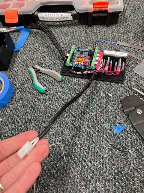
| This is the finished project box - there will be the pump power and ground wires which go to a Molex to power the pump, and the rest will go to a CPC installed in the baggage floor to interface with the aircraft. |
 |
| Whenever i do electronics - there is ALWAYS crap everywhere!!! |
Here is a bit of an overview of how it works:
Edit: A Reliability Improvement
Sitting on the couch having a cup of tea, thinking about failures, got me thinking about how the smoke electronics system could fail. Relays are very reliable - and easy and cheap to replace. However, the Arduino itself is fairly untested in the aviation environment. If the Arduino were to fail, there would no no way to turn the smoke on.
Since i already have a ground coming direct from the 'ON' switch, i figure this is an easy fix. A single wire to connect this ground, to Pin 85 on the Smoke Pump Relay would effectively ground the smoke pump relay directly (purple line) - whether the Arduino was functioning or not. If the Arduino was still functional, and the system was moved to the ON position, a ground for the Smoke Pump Relay would be made directly to the relay, as well as through the Arduino circuit.
However, i would also like to take advantage of the discrete and audio outputs provided by the Arduino when the smoke system is turned on 'manually'. By wiring the 'ON' switch directly to the pump relay, we are not taking advantage of the Arduino. However, with the addition of a couple of diodes, i was able to ground the pump relay (purple line), as well as provide a ground input to the Arduino at the same time (green line). The diodes are necessary, as without them the relay will end up grounding itself through the Arduino - and this is note possible as an Arduino pin can only sink 20ma or so, whereas an automotive relay is 10x that amount of current.
.png) |
| With this improvement I don't need the Arduino to be functioning. Selecting 'ON' will ground the pump relay directly. If the Arduino is functioning, then this selection is sensed by Pin d5, and some isolation diodes ensure the Arduino is not grounding the pump relay. This gives all the discrete and audio outputs from the Arduino. |
To connect the diodes, i followed some advice from the VPX install manual - by forming the diode into a small 'S' shape, and soldering the wires to each end, it has a lot more support than simply soldering to each end of the diode itself.


The outputs of the 2 diodes were soldered together into the ground wire to the ON switch - this is similar to how i will do my CANBUS connections at each LRU - so good practice!
 |
| The 2 wires are fanned out and twisted together. |
 |
| Then the single wire is wrapped around to form a mechanical bond, then soldered. The whole thing is then covered in heatshrink. |
Here are some photos of the final box wiring complete - i split the pump power wires off to come out one side of the box. The main harness of wires will now come out the bottom of the box - with some strain relief in the form of a cable tie to the box lid:

 |
| The wires to the pump are made with a simple cheapo Molex connector. The main group of wires will be terminated in a Series 1 CPC (Series 1 due to the amperage required). |

 |
| Much better strain relief on the wires this way. |
Here is a video showing how the whole system works, including the smoke pump:
For anyone interested is using my code, here it is:
1 2 3 4 5 6 7 8 9 10 11 12 13 14 15 16 17 18 19 20 21 22 23 24 25 26 27 28 29 30 31 32 33 34 35 36 37 38 39 40 41 42 43 44 45 46 47 48 49 50 51 52 53 54 55 56 57 58 59 60 61 62 63 64 65 66 67 68 69 70 71 72 73 74 75 76 77 78 79 80 81 82 83 84 85 86 87 88 89 90 91 92 93 94 95 96 97 98 99 100 101 102 103 104 105 106 107 108 109 110 111 112 113 114 115 116 117 118 119 120 121 122 | //Smoke System Arduino Uno Code - Trent Stewart - Rev 02 - Oct 2023 // - Rev 2 - Revises functionality to allow direct pump relay control by switch in ON (allowing for Arduino Failure) //https://www.tinkercad.com/things/3pj3PEloeqD?sharecode=qgqEMwbGgG94DFb8YggVe8xMMwOtGZJ5L9JfC9pNHkw //Pin Assignments const byte STICK_BTN = 4; const byte ON_SW = 5; const byte ARM_DISCRETE = 8; const byte ON_DISCRETE = 9; const byte TONE_PIN = 12; const byte RELAY_COIL = 10; //System Parameters const int BEEP_DURATION = 200; //Length of Beeps const int STICK_BTN_MIN_TIME = 100; //Sets the Time the Stick Button needs to be held //Variable Definitions bool ON_STATUS = HIGH; //On Switch - low = selected bool STICK_STATUS = HIGH; //Stick Pushbutton - low = pushed bool ARM_SMOKE_ON = false; //false = off Variable to track if smoke relay should activate or not based on ARM bool MAN_SMOKE_ON = false; //false = off Variable to track if man turned on, and beeps should sound or not. bool RELAY_GND = LOW; //Initiates Relay Ground Variable as LOW (Relay Off) int STICK_PRESS_START = 0; //Variable to log time stick button is pressed int STICK_PRESS_DURATION = 0; //variable to work out length of stick button push (in milliseconds) bool ON_BEEP = false; //Used to track if ON beep has occured when SMOKE_ON switches states bool OFF_BEEP = true; //Used to track if OFF beep has occured when SMOKE_ON switches states void setup() { Serial.begin(9600); //Initialise the Modes of the Pins pinMode(ON_SW,INPUT_PULLUP); pinMode(STICK_BTN,INPUT_PULLUP); pinMode(RELAY_COIL,OUTPUT); pinMode(ARM_DISCRETE,OUTPUT); pinMode(ON_DISCRETE,OUTPUT); //Initialise the Status of the Discretes (board boots in Armed mode) digitalWrite(ARM_DISCRETE,LOW); digitalWrite(ON_DISCRETE,HIGH); //Play Startup Tone to Warn system is armed tone(TONE_PIN,200,BEEP_DURATION); delay(BEEP_DURATION); tone(TONE_PIN,400,BEEP_DURATION); delay(BEEP_DURATION); tone(TONE_PIN,600,BEEP_DURATION*1.5); delay(BEEP_DURATION*1.5); } void loop() { //Read the status of each input device (switch or button): ON_STATUS = digitalRead(ON_SW); //This reads inputs from smoke panel switch and stick switch STICK_STATUS = digitalRead(STICK_BTN); //Adjust the SMOKE_ON varable according to switch or button positions: if (ON_STATUS==LOW) { //if turned on manually, smoke on and set variable to track MAN_SMOKE_ON=true; delay(50); } else if (ON_STATUS==HIGH && MAN_SMOKE_ON==true) { //if man on is not selected, but man switched is true, then turn off smoke MAN_SMOKE_ON=false; //this turns off smoke if it was on manually then turned back to arm or off ARM_SMOKE_ON=false; } else if (ON_STATUS==HIGH) { //if Not Selected to ON then if (STICK_STATUS==LOW){ //Measure Stick Press Duration STICK_PRESS_START = millis(); while (STICK_STATUS==LOW) { //Once button is pushed, enter a loop STICK_PRESS_DURATION=millis()-STICK_PRESS_START; //keep updating time until stick button released back to high STICK_STATUS = digitalRead(STICK_BTN); //updates the variable so loop can exit when button is released } } if (STICK_PRESS_DURATION>=STICK_BTN_MIN_TIME) { //if button push time exceeds threshold, then if (ARM_SMOKE_ON==false) ARM_SMOKE_ON=true; //Smoke is Off, Turn it on, beep twice else if (ARM_SMOKE_ON==true) ARM_SMOKE_ON=false; STICK_PRESS_DURATION=0; } } //Actually Move Relay based on the value of the SMOKE_ON variable if (ARM_SMOKE_ON==true) { RELAY_GND=HIGH; digitalWrite(RELAY_COIL,RELAY_GND); } else if (ARM_SMOKE_ON==false) { RELAY_GND=LOW; digitalWrite(RELAY_COIL,RELAY_GND); } //Update the output pins to send discretes to the panel if (MAN_SMOKE_ON==false && ARM_SMOKE_ON==false) digitalWrite(ARM_DISCRETE,LOW); //Armed signal if armed but smoke not on else digitalWrite(ARM_DISCRETE,HIGH); //Else, aka, if SMOKE IS ON then ARMED signal off. if (MAN_SMOKE_ON==true || ARM_SMOKE_ON==true) { digitalWrite(ON_DISCRETE,LOW); //If Smoke if On, Turn on "SMOKE ON" and } else digitalWrite(ON_DISCRETE,HIGH); //Else, Turn off Smoke On (and armed is caught in next run of program) //play tones if (MAN_SMOKE_ON==true || ARM_SMOKE_ON==true) { while (ON_BEEP==false) { tone(TONE_PIN,400,BEEP_DURATION/2); delay(200); tone(TONE_PIN,600,BEEP_DURATION/2); delay(BEEP_DURATION+200); OFF_BEEP = false; ON_BEEP=true; } } if (MAN_SMOKE_ON==false && ARM_SMOKE_ON==false) { while (OFF_BEEP==false) { tone(TONE_PIN,600,BEEP_DURATION/2); delay(200); tone(TONE_PIN,400,BEEP_DURATION/2); delay(BEEP_DURATION+200); ON_BEEP=false; OFF_BEEP=true; } } } |
No comments:
Post a Comment