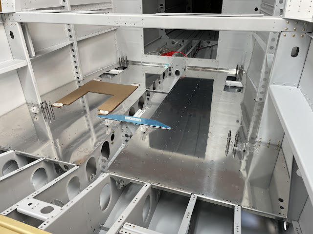
Initial Fit of Baggage Skins
Moving on, i thought it was a good idea to test fit the baggage floor skins to see how they fitted. However, no matter what i tried i could not work out how to get these to go in! They simply would not fit over the seatbelt lugs. The skins felt like they were being snagged by the fuselage side structure - i could not slide them forward enough to get them to slip over the ends of the seatbelt lugs.
I was so annoyed by it - i asked for more help on the forums! However, i needn't have bothered asking. It was just a case of me not thinking things through clearly enough!
It turns out, i had under set the rivets holding the 2 halves of the seatbelt lugs together. The hole in the skins for the seatbelt lug was hanging up on the rivet tail, preventing me sliding the skin forward enough to get it to slip over the ends of the seatbelt lugs. I had thought it was hanging up on the fuse side structure.
Once i squeezed the rivets a little more, the forward part of the skins could be bent upward, and this allowed the whole skin to slide forward and pop over the end of the seatbelt lugs. They fit very easily actually.
Oops.
Baggage Tie Down Rings
Van's sells baggage tie down rings but i was able to source some BOAB OLTD5 - Tie Down Ring and Base. These take a 1/4" countersunk screw, so i purchased some AN509-416R11 structural screws, and corresponding nutplates - MS21047L4K.
The nutplates have a 1" space between rivets, and the tie down ring bases also have a 1" space between the mounting holes. The idea is that i will make up some skin doublers using some sheet i have the same thickness as the skin. The doublers and the nutplates will be backriveted to the skin before the skin is installed with pull rivets. Then i can just screw the bases in after the cockpit is painted (and they can be removed at a later date if required).
I started by laying the baggage skins in place and working out a plan for where the tiedowns could go, and where i was able to fit a doubler under the skin which would not interfere with any of the underlying structure.
I elected to place a pair of tie downs just next to the seatbelt lugs, as these would end up out of the way of where i wanted to mount the smoke tank, and another pair in the very after outboard corners of the floors.
 |
| Baggage floors finally in place! (headslap) |
 |
| The nutplates show the approximate location of where the tiedown will end up. |
 |
| This is where the forward bases will go - adjacent to the seatbelt lugs. Also shown is the first go at laying out a doubler, by just marking it out with a pen. |
Tie Down Doublers
The process to accurately make the doublers was interesting. Initially, i just marked out where the holes needed to be and drilled on my marks. I did not back drill using a nutplate etc. What i ended up with was a set of holes very slightly out, such that the rivets did no go in straight. I needed a better system!
What i ended up doing was following the process below:
- I cut a piece of sheet the same thickness as the skins, to act as a drilling template and marked where i wanted the 2 screw holes to end up using a #40, and drilled these. These were marked to be 1" apart, using calipers.
- I laid out and drilled 2 other rivet holes, which will serve as reference holes in the initial stages, but will end up being rivets.
- I then drilled these 4 holes into another sheet of aluminium the same size, which will act as a sacrificial template piece.
- I took the sacrificial template piece and up-drilled the 2 holes where the screws go to 1/4".
- I used a spare AN4 bolt and screwed this into a nutplate. I then cut the head off the bolt with a dremel, cleaned it up, and added a slot in the head for screwing it back out later.
- I was then able to use this as a nutplate jig in my sacrificial template piece, to drill the rivet holes for each of the 2 nutplates.
- Once i had the sacrificial template piece made, i then clecod it to the first template piece using the 2 reference holes. I was then able to accurately transfer the nutplate rivet hole locations
 |
| Here is the drill template on the bottom, and the 2 doublers on the top. They have the 2 reference holes in the middle vertically, and the 2 screw holes already drilled, but no nutplate attach holes. |
 |
| This was the home made nutplate lig |
 |
| The nutplate jig was used to match drill the nutplate attach holes to a sacrificial template piece. |
 |
| A test fit shows the drill template works great. |
 |
| One screw hole was drilled in the skin in the required location, then the drill template was clecod on and match drilled. |
 |
| The positions of the clecos show the locations of the tie down ring bases. |


No comments:
Post a Comment