The stock RV-14 canopy latch which ships with the finish kit, is the same as other models of RV such as the RV-7 etc and is functionally a very good design - albeit not very aesthetically pleasing!
However, many RV-14 builders have been installing the JD Air Custom Tip-Up Canopy Latch, and i have decided to also install this product.
The main task when installing this is to cut a larger hole in the side skins - so Chapter 29 is the correct time to tackle this, before the skins are primed and dimpled etc. Much easier to do it now than after the skins are attached to the fuselage.
I was understandably nervous about cutting holes in such a large component such as the side skins, so i decided to make up a facsimile of the skin in the handle location (a test skin) and fit the handle to this piece first. Once correctly fitted, this would also allow me to use the piece as a cutting template.
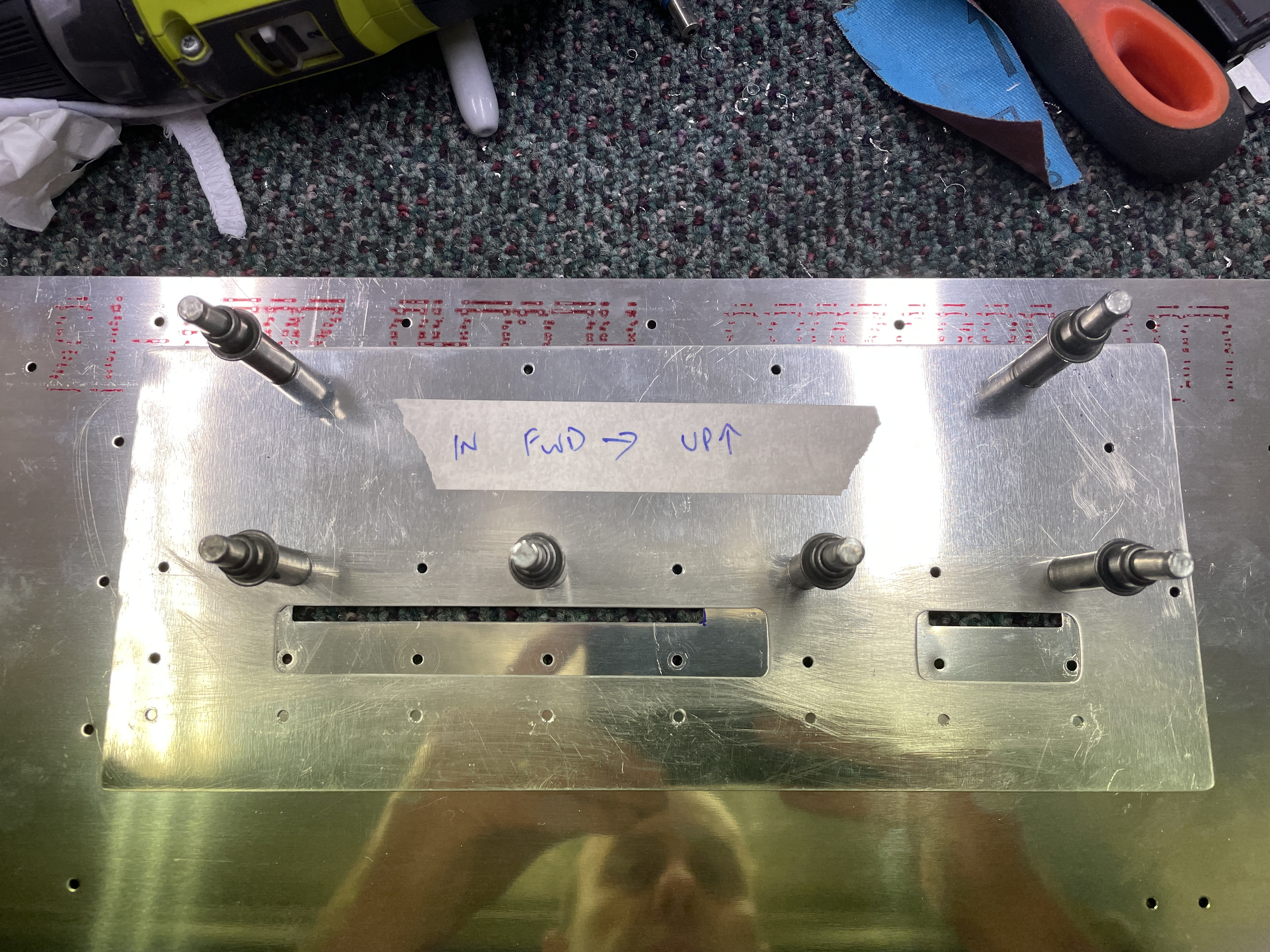
First step was to install the upper longeron onto the side skins and flute the canopy latch attach brackets to match the existing holes in the side skins - it was probably overkill, but the skin here does have a very slight curve to it, so i thought it best to make sure the brackets were curved to match the curve of the skin with the upper longeron in place (rather than flat on the bench).
 |
| The holes in the canopy latch brackets did not match the side skins at all. |
 |
| After some fluting, they brackets matched perfectly. I did this with the upper longeron attached to the skins as the skins have a slight curve in this area (matching the upper longeron). |
 |
| Holes lines up after fluting. |
Making up a test skin
Next up, i cut a piece of 0.025" thick sheet i had in the shop such that it was tall enough to engage with the lower line of holes in between the skins and the upper longeron, and wide enough to cover all the holes in the latch attach brackets. The side skins are 0.032" but all i had was 0.025". The piece was taped in location, and i then match drilled holes along the upper longeron line (for registration), as well as all the holes along the latch attach brackets (clecoing as i went).
 |
| I marked the location of the existing latch holes onto the test skin. |
JD Air Instructions and Drilling Template
However, as you can see from the below image, when you align the cut-outs in the template over where the existing cut-outs are, the bracket attach holes called out in the template do not match the holes in the RV14 skins. I guess this is a general hole layout template and is not aimed at the RV-14. Basically all it did was give me some rough guidance as to the size and shape of the holes (and their location relative to each other).
The issue here, is these holes need to be cut in a location which is accurately related to the holes in the mounting angle brackets. If there were no holes in the mounting angles, i could just put the handle cut-out holes anywhere and match drill the attach brackets to the skins. However, since the top bracket is installed in holes which are already located in the top bracket and the skins, i needed a way to accurately place the cut-outs for the handles in the correct location.
The solution was to make up the handles using the called out hardware. The hardware is called out in the
drilling template document. As you can see below, the plans call out the use of "AN960-10L" washers between the handles and the attach brackets.
I decided to mock-up the handles and the brackets and discovered a couple of things - the AN3-12A bolts seemed way to long for my parts - i think AN3-11A bolts are a better length. For the mock-ups i used some AN3-11 (non drilled) bolts while i wait for the drilled bolts to arrive.
Secondly, the AN960-10L washers are NAS1149-F0332P washers - which are AN3 size hole and 1/32" thick. Since the top edges of the existing holes in the skins are aligned with the bottom surface (bearing surface) of the existing top hinge bracket, this meant a 1/32" (0.032") gap above the handle to the skin. To make it look decent, i would have to make the gap 0.032" all the way around the handle.
 |
| This is the 1/32" (0.032") gap if i used the NAS1149-F0332P (AN3, thin washer). I thought it was too big to have this all the way around the handle. |
I thought that this was just too big a gap, so decided to do try using some 0.016" thick (1/64") material i had laying around to make up 4 shims to use in place of the washers. These are half the thickness of a NAS1149F0332P (AN3 thin) washer.
I then put the handle back together with the brackets and i felt the gap would look a lot better being smaller:
 |
| 0.016" (1/64") gap looks a lot better in my opinion. |
Cutting the Holes for the Handle in the Test Skin
Now that i had established the handle and it's shims, which set the correct distance between the handle and the upper and lower mounting brackets, i was able to put the handle together using bolts and finger-tightening the nuts. I now needed a way to locate where the handle cut-out holes needed to go in relation to the upper bracket and it's already drilled holes. I tried clecoing the handle onto the test skin and tracing around the ends of the handle, but this was sketchy to say the least! Not very accurate.
In the end, the method i settled on drew from my experience at kindergarten! I simply taped a bit of paper onto the handle and bracket assembly, and traced the outline of the handles. I then 'match drilled' the paper template to the holes in the upper bracket. This then allowed me to mark a 1/64" gap (0.016") around the whole handle, and created a nice handle cutting outline which fairly accurately referenced to the holes in the upper bracket.
 |
| 1/64" (0.016") line drawn around the bracket. |
 |
| A washer was used to draw the corner radii |
 |
| I centre punched where i needed to drill at the ends |
The handle holes were cut out of the paper, and i could then align the top row of holes which the holes already drilled in the test skin, and draw the planned cut-out onto the test skin.
 |
| The template was cut out, and the planned outline of the cut-out was drawn on the test skin. |
To cut out the holes, i marked the ends of the handle cut-outs with drill marks, which were drilled to #40, #30 and then 3/16" (reamer) in order to gang drill the ends of the handle cut-outs, as they were too narrow to get the Dremel safely into position. I used a Dremel for the straight runs of the top and bottom lines. I then filed to the lines, test fitting the handler as i went.
Overall, the fit to the test skin was pretty good. The tops and bottoms were almost perfect, but i filed a bit too far on the ends. The test skin was still a success - when i cut the holes in the skin proper, i will go a bit shy of the test skin cut-outs at the ends and gently get the actual skin to the correct size - i only get one go!
 |
| Filed a little too far at the ends. |
 |
| The test skin fits the actual skin very well - and will encompass the existing handle cut-out holes, as well as the existing holes in the bottom row (where the original lower bracket was supposed to go). |
Making the big cut in the skins!
There was nothing left for it - time to cut the skins!
I started by using the paper template to mark the locations of the 'gang drill' holes at the end of the slots.
I then placed the test skin in position and started by match drilling the locations of the lower bracket holes to the skin, on order to give me more cleco locations to keep the test skin steady.
I then drilled #40 holes in the ends of the slots where i could, and increased the hole size to #30 then 3/16" (reamer).
I used the Dremel to cut the long slots and gently filed until the skin hole matched the test skin hole. The ends of the holes were left short, and removed the test skin then fitted the handle in place and filed iteratively until i got a good fit. Overall i am very happy with how this modification turned out. It's a really solid latch.
 |
| I used the paper template to mark the locations where i would drill to remove material at the ends of the slots. |
 |
| End of the slots 'gang drilled' |
 |
| Not scared at all. Not even a bit. {gulp} |
 |
| The ends of the slots were left short as compared to the test skin. |
 |
| Initial fitting allowed me to use marker to denote where material had to be removed - slowly - in order to get a good fit. |
 |
| The blue marker shows where i need to remove more material. |
 |
| This was completed in a couple of rounds until the latch fitted nicely and gap seemed as even as i could get it. |
Edit: For the little hole which is left over between the small and large parts of the handle. For anyone following - mark the hole location into the handle at this point (even match drill #40 a little depression into the handle). I did not do this, and had to transfer the location of this hole (with the dimple and rivet) onto the skin afterwards. Way better (and more accurate) to do it now.
 |
| So nice and flush with the skin! |
 |
| This is the final gap i was able to achieve. Compared to the #40 holes below, i am very happy with how small and consistent the gap ended up being. |
And of course - i had to test it out!

.png)


.jpg)


No comments:
Post a Comment