The time has come to rip this thing apart! I took some basic tools into the shop and with some great guidance from Jack, the head of the engine shop, we pulled the entire engine apart. You literally can't pay for this experience. It was great! As a pilot who has flown behind these things for years, i am ashamed to say i couldn't recognise what any of the bits and bobs hanging off the case were - now is the time to work that out!
Some basic rules were set - all plain nuts and washers, gaskets, split pins, safety wire etc was to be chucked into the 'bin bucket' - we didn't go straight into the rubbish bin, but kept everything, just in case we needed to refer to it later.
We kept all the bolts, as these are a coarse thread bolt, specfic to the engine (not normal AN fine thread bolts). We kept all the castellated nuts, and all the little bits and pieces, like brackets etc. For some parts, such as the pushrod tubes, we kept some components (like the seal retainers), but threw away others (like the twist lock spring plates). All little cheap screws (like from the rocker covers) were thrown away. The part to be kept were put into a cleaning bucket to go into the hot wash and decarbonising wash later on.
As i pulled everything apart, we tried to keep it all organised on the bench. Jack didn't want me to record any part numbers - because the whole engine was coming apart (with new cylinders), there was no need to pay attention to where everything went.
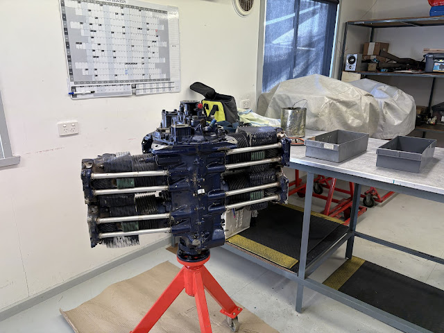 |
| BEFORE! |
Time to pull it apart!
Valve / Rocker Assemblies
I started off by removing the rocker covers. These were just simple slotted screws with star washers.
 |
| So retro! |
Next i removed the covers from the rocker shafts (14), and turned the engine so that the piston was at top dead centre in that piston, which took the pressure off the rocker arms (4,8). You could tell becuase both rockers could wiggle up and down. Once they were free, you could push the rocker shafts out with your finger. The rocker (4,8) and a little washer (10) fell out at the same time. I found the easiest way to get the piston to top dead centre was to just look in the intake and exhaust holes, and rotate until both holes were closed.
On cylinders 1 and 3, i was not able to get one of the rocker shafts out (between the 2 cylinders on that side) as it hit the stud for the opposing rocker shaft cover. I was able to get it back enough to get the washer out, and then the rocker had enough space to come out. I just left the shaft floating in position until i removed the cylinder.
 |
| The rocker shaft would not come all the way out, but came out enough that i could push the washer out of position on the oppisite side of the rocker, which allowed the rocker to slide off the tiny bit of shaft sticking out. I left the shaft floating in position until we removed the cylinder. |
Next I removed the pushrods (1), by just pulling on them.
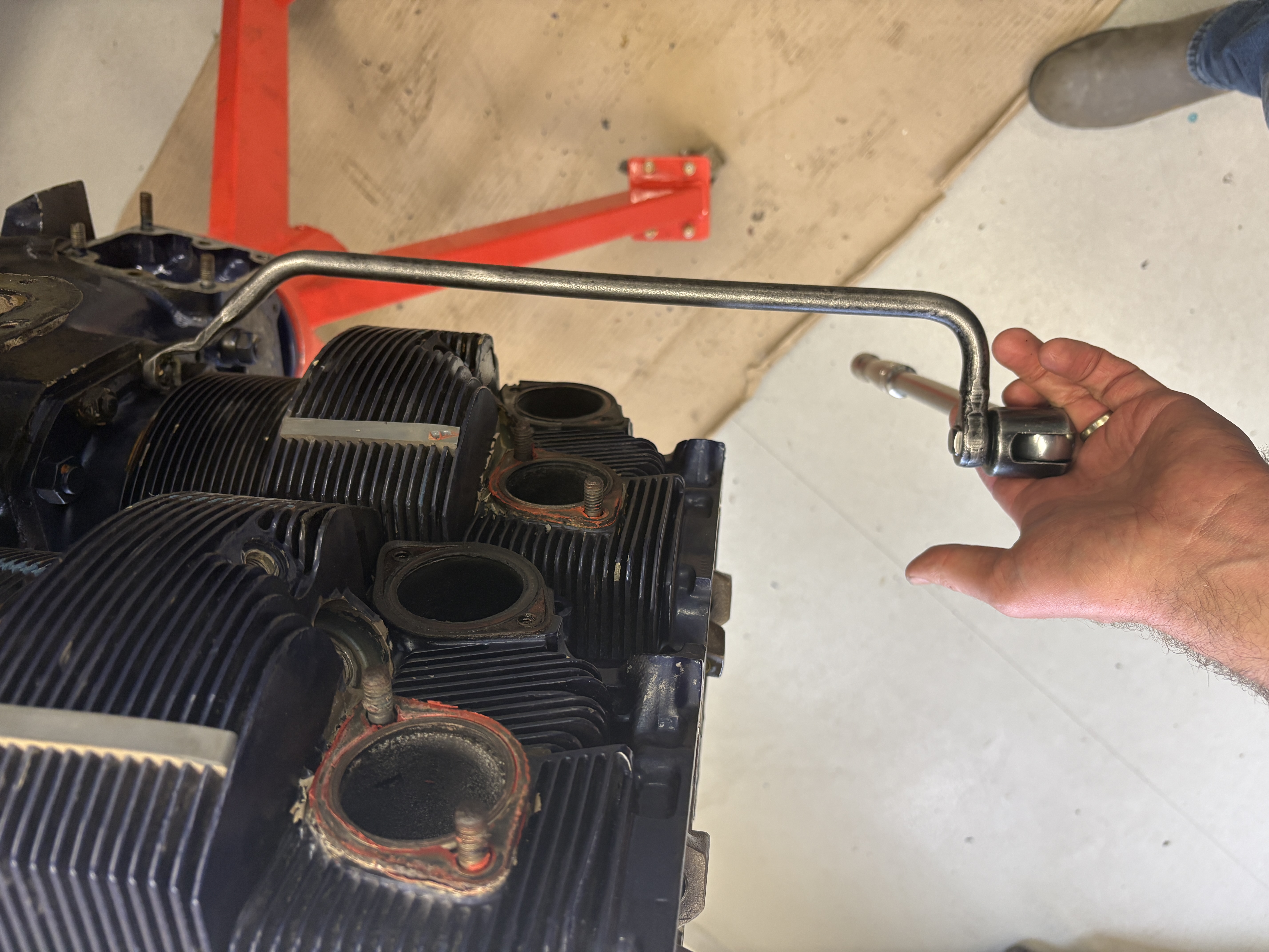
Next, I removed the pushrod shroud tubes (15). These were a little tricky and it wasn't obvious how they came out. I was not able to use any tools on them, as i did not want to damage them. To start, you get a pick and insert it into the hole into the end of the shroud tube spring (16). It rotates and allows the shroud tube to loosen. You can then push the tube back toward the engine (with all your might!) and eventually the tube will pop out of the hole at the cylinder top end. We threw away the green rubber washers (21) and the springs (16), but kept the washer (19) and shoud tube sleeve (20).
.png)
Accessory Case
Next up, i tackled the sundry on the accessory case. We did this before removing the cylinders, as some of these fittings had been in the case for many many years, and were pretty difficult to get out. Having the cylinders in place allowed for a good hand hold to really wrench on the spanner. (or spanner on the wrench if you are in the US?).
 |
| This was a reference photo for the orientation of all the fittings. |
For reference, i found a good diagram (thanks KitPlanes!), showing what all the various parts on the back of a Lycoming are for:
 |
| Another reference photo. |
To get the really stuck fittings out, i applied some heat around the fitting. The hear was applied to the accessory case, trying to keep the heat off of the fitting itself. They all were able to be unscrewed using this method.
In the above photo, i am removing the fitting which feeds the oil cooler (the oil pump outlet), and i have removed the oil filter base assembly (part 77852). This is the fitting where you screw in the oil filter, and it contains the vernatherm which bypasses the oil filter when the oil is cold. Inside it has a little clip which holds a spring, which is held by a screw into a threaded fitting. On my adpater, the threaded fitting had loosened and backed out. So we will likely need to repair this, or get a new base assembly.
 |
| This is the side that the filter screws to. |
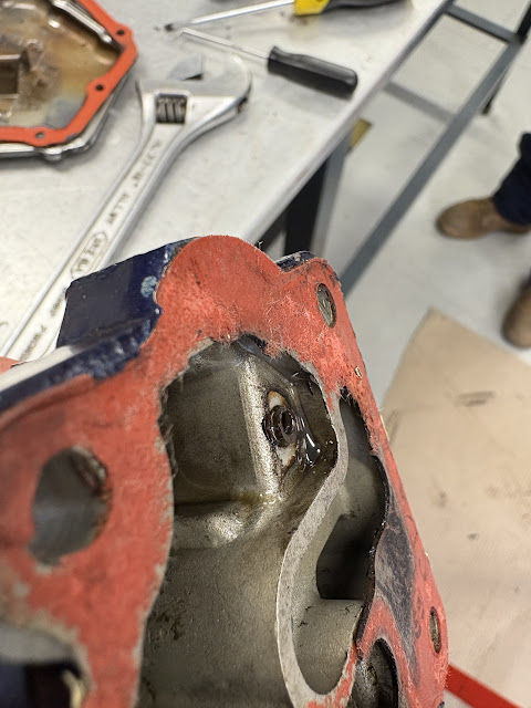 |
Here you can see the little rusty threaded insert had backed out.
|
 |
| You can see the clip on the left hand side - the rusty fitting which had worked its way out was under this. |
Next up i removed the vacuum pad drive assembly. I will re-use this to drive the Monkworkz MZ30 generator.
Removing the Cyliners
Now came the fun part - removing the cylinders! Of course, this is not possible without the famous cylinder base stud wrenches - we used 2 sizes, one for the big through stud nuts, and one for the smaller cylinder base stud nuts. This part was pretty fun, and was fairly straight forward. There was one position where the nut was seized on the stud, and the stud backed out. No big deal apparently - we can re-install the stud later.
SHOP TOOL COUNT: 2
 |
| This rusty nut was seized, and backed the stud out. |
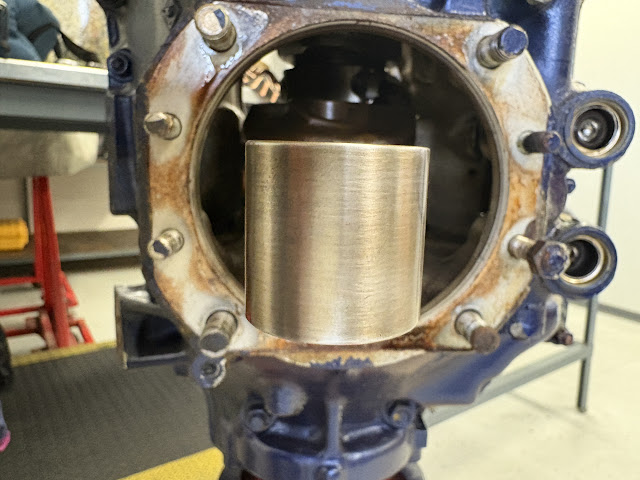
Once i had all the nuts removed, the cylinders just sort of sat there in place. We had to make sure we didn't accidentally rotate the engine at this point, lest a cylinder fall off! We were also cautious to take the cylinders off evenly on each side - we didn't want 2 cylinders on one side, and none on the other, or the engine may topple over.
Of course, had to take a quick look inside. They aren't as bad as what i thought, although they are P10 cylinders and pistons (as evidenced by the green paint on the engine, and also the P10 stamped onto the piston part numbers!).
Next, i used a shop tool which was designed to fit over the piston pin caps, and punchout the piston pins. I had to be careful when the pin began to move back inside the bushing on the little end of the conrods. If the tool bent sideways, i could impact the conrods, which would be bad! The pins came out a lot more easily than i was expecting.
SHOP TOOL COUNT: 3
 |
| At this point, the pin is punched back inside the conrod bushing. I had to make sure the punch was straight, and inside the conrod bushing, and not cocked off to the side. Or a whack with the hammer could result in a new 4k conrod being needed. |
These pistons are mandatory replacement parts. If anyone still smoked, i would have some awesome ashtrays to give away.
Once the pitsons had been removed, we took some brake cleaner and a scotchbrite pad and cleaned up the conrod ends a bit. One of the things i was afraid of, was moisture entering the engine through the case breather, or through the open valves. As you can see below, 2 of the 4 conrods have some corrision on the tops. We will have to cross our fingers on this one. New conrods are expensive.
 |
| I wish they all looked like this. |
Removing the Accessory Case Cover
Next up was to remove the accessory case cover. This was fairly straight forward - bolts all the way around, and a couple of bolts from the forward side. The cover loosened with a whack of a plastic mallet on the interior face (from where the sump would have been).
 |
| These are reference photos for where we need to paint later. |
 |
| We gave it a whack on the inside under here. |
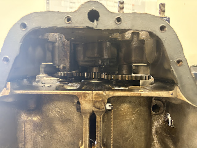
Once the accessory case was removed, the idler gears just slid off. Underneath was the idler gear shaft (18) which came off with a couple of nuts and bolts (these nuts were retained). As i am noticing in this engine, it is often the case that things are held on with a mixtire of studs and nuts, and bolts threaded into the case. There is probably a reason why!
.png)
SHOP TOOL COUNT: 4
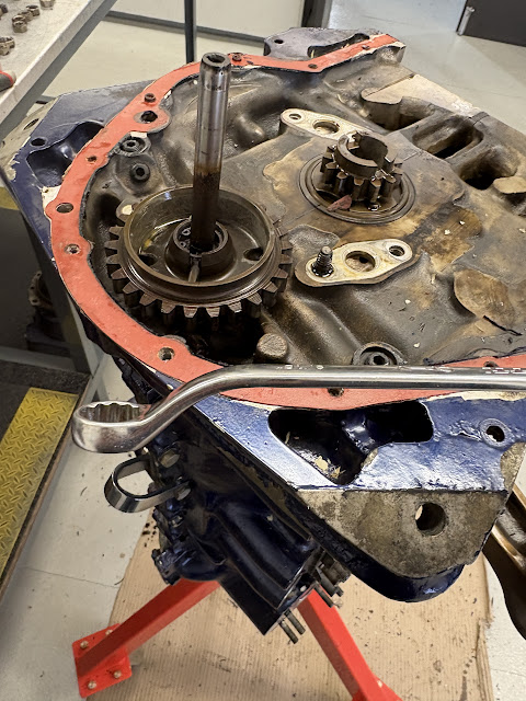 |
| This spanner makes short work of that nut. |
In order to split the case, you need to remove the through bolts. The case has a couple of studs which are attached to the RIGHT hand side of the case (not numbered), and poke through holes in the left of the case. There are 4 through bolts (20) which need to be pulled totally out, and at the front of the case there are an additional 2 fasteners - the top one (labelled as 12,13,15 etc) is a stud which (on this engine anyway) is in the LEFT side of the case, and has a nut. The bottom one was a through bolt (15), with the head on one side, and the nut on the other! Who knows why!
 |
| This was one of the 4 through bolts (20) |
To get the through bolts out, we used a home made slide hammer (of sorts). The bolts came out fairly easily.
SHOP TOOL COUNT: 5
 |
| This is the shop made slide hammer, with a through bolt screwed into the end of it. |
It is farily easy to attach the slide hammer tool to the wrong stud. You realise as soon as you whack it that it feels too solid - you are screwed onto the wrong thing! I ended up just looking or feeling inside the case before i whacked it, to make sure that it was a through bolt and not a stud.
Actually splitting the case!
To split the case we needed another shop tool! (i am counting this as one tool, but was more like a box of them!) In basic terms, you need to push the left case half away from the right case half. To do this, you bolt a plate onto the left side of the case to act as a stop. You then bolt a matching plate to the right side of the case. It has holes in it, which align with the through bolt locations. You then screw a through bolt into the right hand plate, and as you are screwing it in, it pushes on the left plate and pushes the case halves apart.
I was very impressed with the shop procedure here - the through bolts which are used to push the case halves apart, are old through bolts. We don't want to get them mixed up, so the real through bolts were put aside and wrapped in a plastic bag, before the case splitting tool even came out of the box. Good stuff.
SHOP TOOL COUNT: 6
 |
| This is the left plate which is attached to the fixed studs on the left hand side of the case. |
 |
| Here we are cranking down on the 'tool' through bolts to push the case halves apart. |
 |
| A teeny split! |
 |
| A vertitable chasm! |
 |
| A gorge! |
 |
With crack, it was split.
|
The case halves were then carefully lifted apart, making sure not to drop out any tappets, or the camshaft. Left behind was the lonely rotating assembly. We had to chop the crankshaft forward seal with some side cutters as it was stuck pretty well into one case half.
Now that is was apart, the reason for this engine being removed from service revealed itself! A bunch of the tappet faces are toast!
Simiarly, the corresponding cam lobes are also toast! The lobe with the white mark was worn down at least 5mm!. The edges were so sharp, it would cut your finger (and had visible burrs).
 |
| This is the very very worn down cam lobe. |
 |
| This is the shape it should be! |
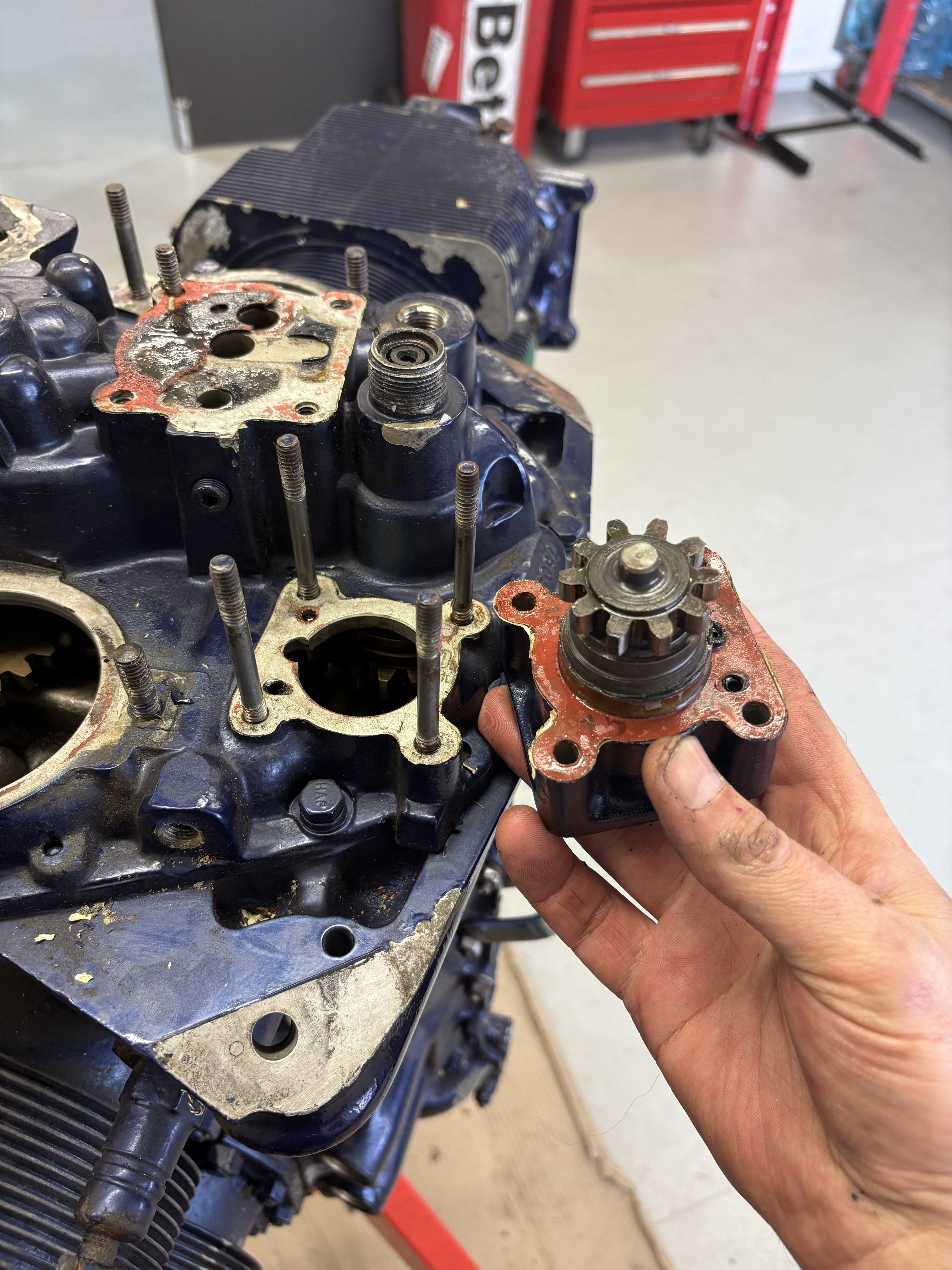
There had celarly been metal go through this engine. So we removed the oil pump housing and gears and had a look inside there. Major scrathces and damage - i think we will likely need a new oil pump housing.
 |
| The scratches are a result of the tappet and camlobes going through the pump in chunks! |
Some case fretting was noted, so we are likely going to need some case machining and line boring here.
 |
| This is the left case haf. Showing the front forward upper through stud. |
 |
| This is the right case half, showing the aft 2 through studs. |
 |
| We were always going to replace the cam - but this one was worn badly anyway, |
 |
| These tappets have had a hard life! |
 |
| The oil pump gears are mandatory replacment parts anyway. |
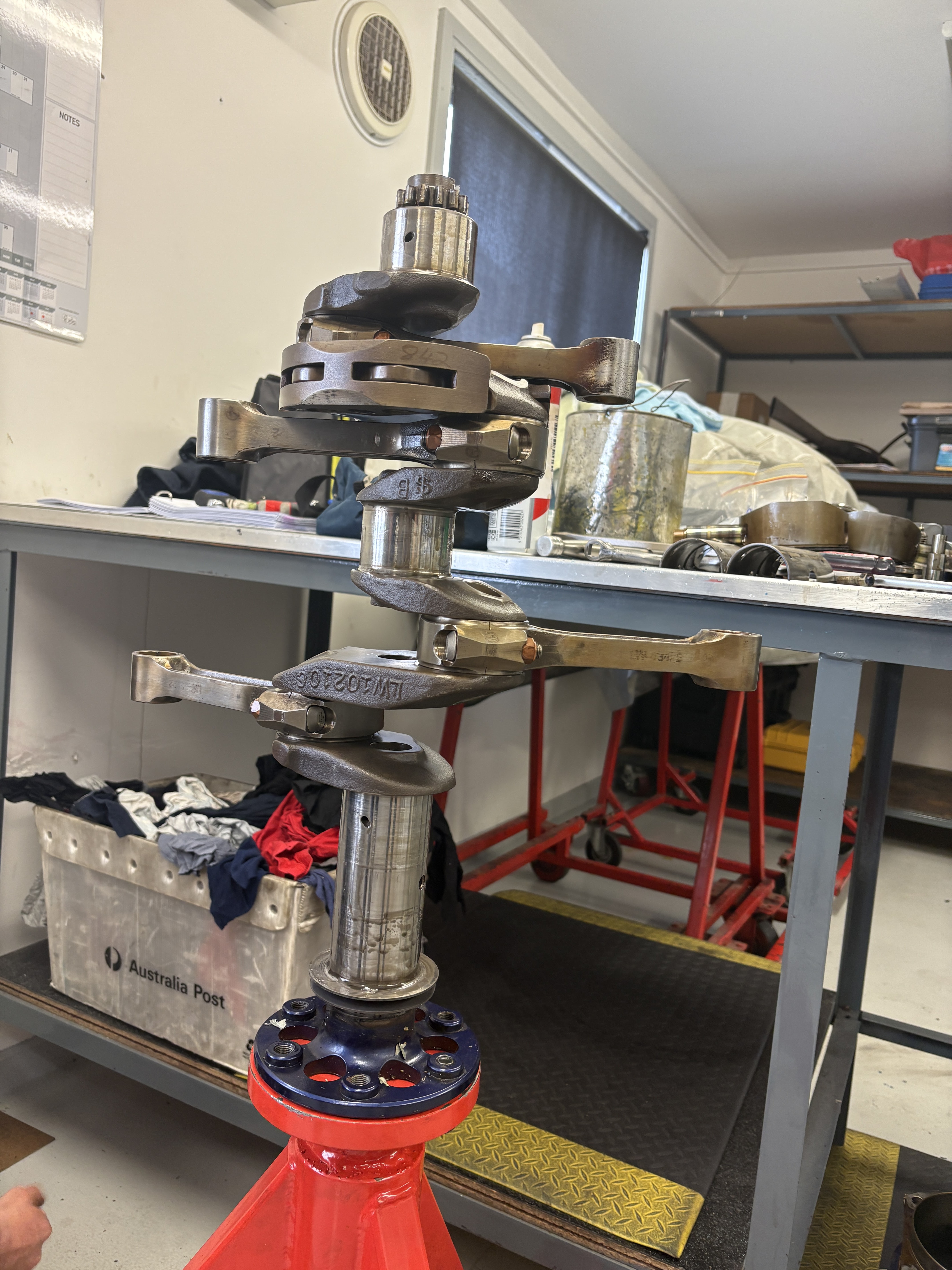
The conrods were removed. Jack recommended i always wear gloves when handing the conrods and the crankshaft - he has seen fingerprints and whole hand prints result in corrosion on these parts when the engine comes back for overhaul at TBO.
To remove the rod end nuts, i needed to use a very long bar and a ground down socket. This one has seen a few dozen engines (or more!) and had a few cracks along the ground down edges. I suspect it is nearing the end of it's conrod nut life.
SHOP TOOL COUNT: 7
Once the conrods were off, we removed the circlips which hold in the counterweight caps and pins. These were removed with a magnet of exactly the right size.

 |
| Before and After! |
So far, the list of parts (in addition to the mandatory replacement parts) we will need to replace are:
- Camshaft
- 4 x Cylinders
- Oil Pump Housing
- Oil filter base assembly
- The gear on the end of the crankshaft
- and fingers crossed on 2 x conrods!
For those playing at home:


.png)


.png)


.png)


.png)


.png)


No comments:
Post a Comment