Finally back to some construction! First up was to dimple all the various components as called out in the instructions - i went through the pages and dimpled each one as required.
 |
| Most components could be dimpled with the squeezer, but there were a few holes in the sub-panel which needed the DRDT2. |
Then went back to the start to begin the riveting. First up was the stiffners on the forward ribs, as well as the doublers for the gas springs and canopy hinge components.
 |
| I was able to reach this stiffner using the squeezer for all rivets. |
 |
| This is the doubler which takes the bolts which hold in the brass canopy hinge components. |
Next up was the smaller, triangular canopy hinge rib doubler - this holds the doubler for the other side of the canopy hinge brass component.
 |
| This has some temporary bolts placed in the holes to align the parts for riveting. |
Next up was the canopy hinge block bracket (where the plastic block holding the canopy release mechanism is installed) and the centre skin rib. The plans ask you to install the rivets which attach the bracket to the rib first, then install the nutplates. Reading the plans, i thought they called out the use of CCR-264SS-3-2 rivets for the lower 2 nutplate rivet holes, and solid rivets for the upper 2 nutplate holes. I was not really sure why, as if i attached the nutplates to the hinge block bracket first, then attached the centre rib, i would be able to just use solid rivets on these, So i went ahead and did this, only to find there is no way to reach the rivets between the canopy hinge block bracket and the rib, if the nutplates are already installed.
So i drilled these out, attached the rib to the hinge block bracket as called out in the plans, but then found i was not able to reach the rivets for the closest nutplate to the rib, with the rib installed!!
Reading the plans again, i realised i had read the rivet call out wrongly - it actually calls out the use of the CCR pull rivets on the nutplate CLOSEST to the rib, and solids on the other one. Clearly this is because you can't reach them with the rib installed! So i made myself work because i can't read the plans. Sounds about right!
 |
| The plans show the use of the CCR rivets for the nutplate closest to the centre rib - i misread this as being the lower attach hole in each nutplate as a CCR, with the upper attach hole as a solid. RTFP (Read the f&%$ing plans!) |
 |
| I used a bolt to hold the nutplate in position to set the rivets, as the nutplate attach holes are countersunk. When done in thin material, this can slightly elongate the hole, meaning the rivets may not align the nutplate with the bolt hole very well. So i use a bolt in the nutplate to ensure it gets riveted into the right location. |
 |
| With the nutplates attached like this, you can't reach the rivets to attach the centre rib. The nutplate on the right should have been installed with pull rivets. |
 |
| Here i have drilled out the rivets for the nutplate closest to the centre rib, as did it the way the plans asked me to! The CCR rivets are special nutplate attach rivets. They have almost no strength - they feel very soft to set - all they do is stop the nutplate rotating when you install the fastener. |
Next up i jumped forward into the remote canopy release plans, and attached the canopy release cable bracket to the centre rib.
The map box doubler was also attached using the squeezer.
I then went ahead and began riveting all the ribs forward of the sub-panel to the sub-panel, as well as the stiffner on the aft side. These were done with the gun and bar - for small AD3 rivets, i use a low setting on the gun - around 30psi. This sets the rivet in about 6 hits.
 |
| These ribs had 4 flush rivets on each side - done with the swivel mushroom set. I clamped the assembly to the bench so it didn't move around. |
 |
| The single AN470 (dome head) rivet was able to just be reached by removing the spring on the gun and protecting the sub panel surface. |
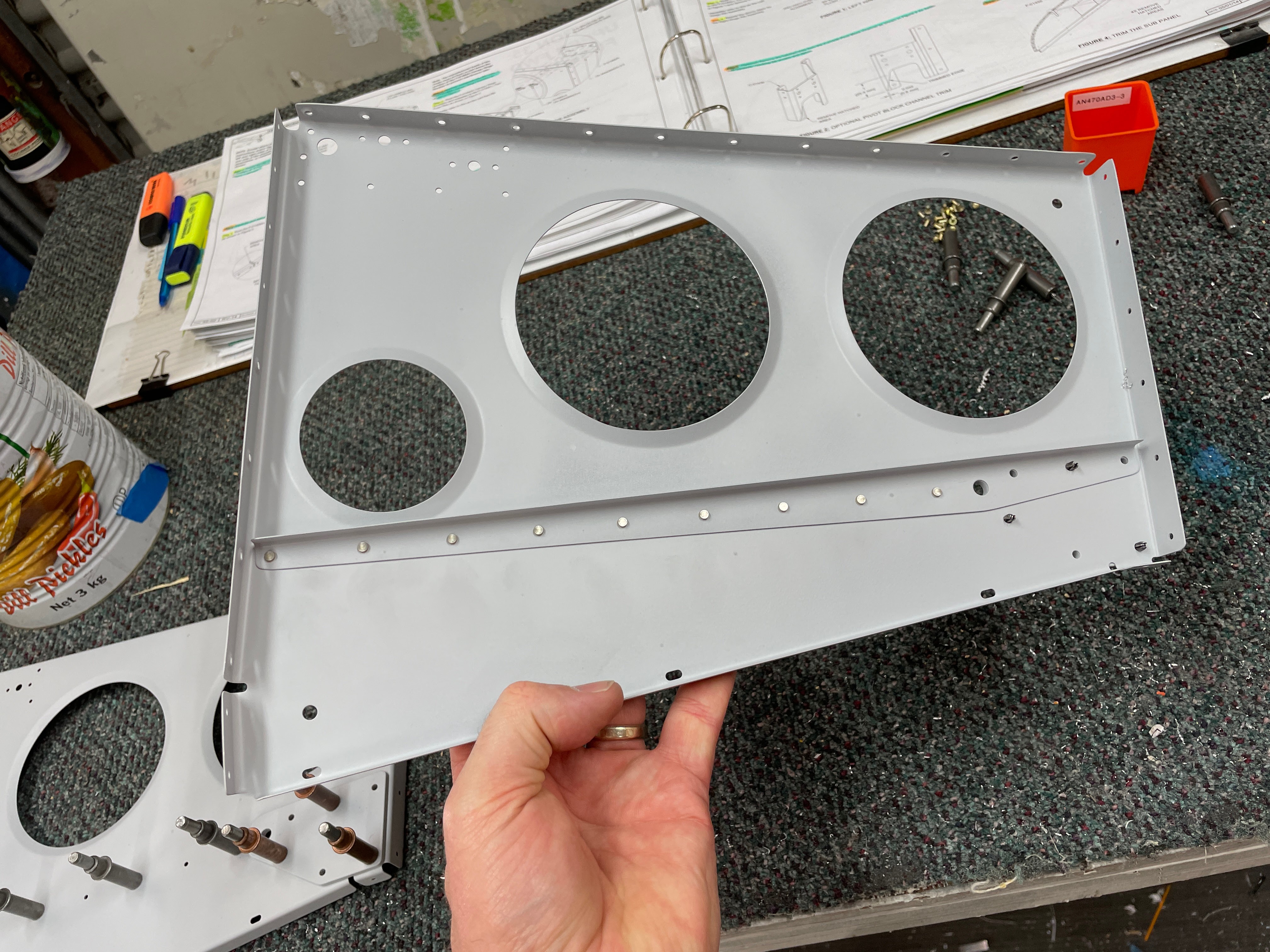
Instrument Panel Standoff Ribs / Molex Brackets - change of install order
On the aft (cockpit) side of the sub-panel, there are 2 x instrument panel standoff ribs. These were simple to rivet on using the gun and bar. The inner surfaces of these ribs form the 'radio stack' area of the panel, and hence all rivets installed need to be flush on the inner surfaces. In the corners of these ribs are 2 tiny little brackets. These have holes in them to take a Molex connector. I have not idea if they are there simply to hold the connector, or if they serve some structural purpose. In any case, they are attached to the standoff ribs using flush rivets. The aft most (cockpit side) one was able to be reached with the pneumatic squeezer, but i could not reach the one closest to the sub panel. I was **just** able to reach using my hand squeezer, but bent over one of the rivets which needed to be drilled out using a 90 degree angle drill.
In hindsight, i see no reason why these brackets could not have been attached to the standoff ribs
BEFORE the ribs were attached to the sub-panel. It would have made setting the flush rivets a whole lot easier.
 |
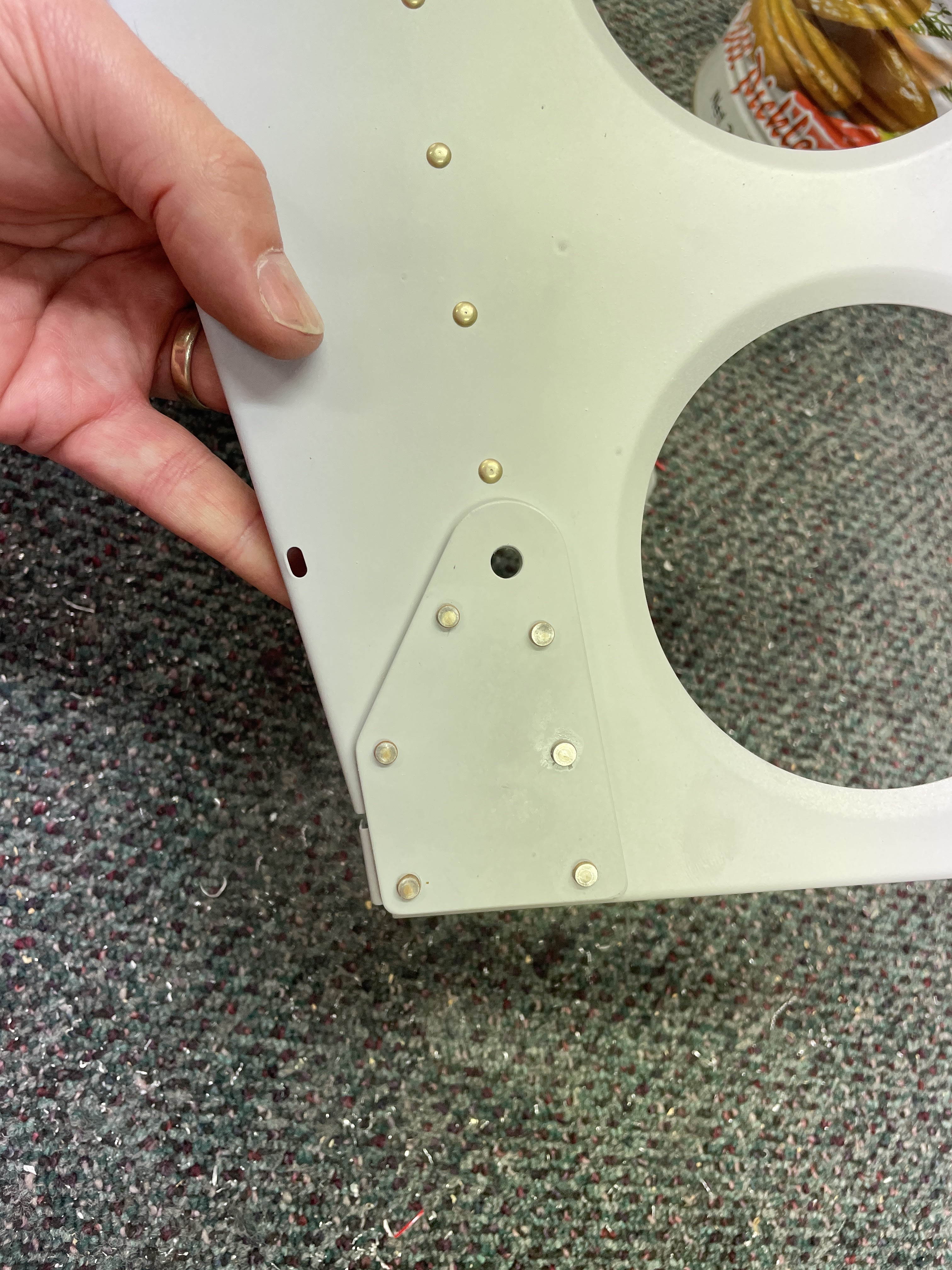
| The pneumatic squeezer was able to reach the aft most flush rivet between the little bracket and the instrument panel standoff rib. |
 |
| The rivet being pointed to would have been easily able to be set with these little brackets already in place - i suggest anyone following to rivet the brackets to the standoff ribs first (the bracket could be easily flexed out the way), then rivet the standoff ribs to the sub-panel. Finally rivet the bracket itself to the sub-panel. |
 |
| I cooked this one! |
 |
| 90 degree drill to the rescue! |
 |
| Finally installed! |
I then attached the canopy seal flanges to the top of the sub-panel using the squeezer.
Sealing the Sub-Panel against rain / Preparing to paint the sub panel
Much later in the plans, on page 35-22 Van's has you proseal on the forward top skins, and run a bead of sealant along the top edge of the canopy seal flange. I have decided that i want to paint the sub-panel the same colour as the cockpit, as this will be visible when the canopy is open. I didn't want to paint this area, then have to seal it at a later date - it would look average, and i was not certain the sealant would adhere to the glossy cockpit paint.
So i installed the upper skin to work out where this sat on the sub-panel flanges, and marked it with a pencil. Then installed tape to outline the edges of the sealant, and applied the sealant to the flange. I will let this cure, then paint the sub-panel up to the line i marked (or a little way past). This should leave me with a neat painted flange (hopefully). At a later date, when i rivet on the top skin, there will just be a small area of sealant to be painted over at the flange gaps of the top skin and the subpanel. #futureTrentproblem
 |
| Here you can see the notches in the canopy seal flange which need to be sealed up - you can also see the notches in the sub-panel flanges (under the blue forward skin). These will be sealed from the inside when the skins are riveted on. |
Once the sealant is cured, i will mask off the sub-panel flanges at the line where the upper skin will be located, and paint the aft face of the sub-panel etc.
Next up is to prep the remaining components of chapter 35, then i will do all of the cockpit painting on one go, before they are installed into the aeroplane.


No comments:
Post a Comment