The stock kit RV-14 hoses are made up of some kind of plastic tubing and brass compression fittings. The bulkhead T-fitting is made of plastic and is of the push-fit style (like was used on the static system). I have heard that this system works fine - but it just seemed a bit dicky to me. I decided to 'upgrade' to braided PTFE hoses.
One great option is to use the TS Flitelines hose package - when setup for a Matco park brake valve, this is a little over $1000USD. Once landed in Australia, with currency conversion, added shipping and GST (tax) this is close to $2000 AUD for a few hoses. I just couldn't justify this. Too many AMU's which can be used elsewhere (like shipping the finish kit).
So i made up a plan for how the system would be plumbed. This was based on using racing car components in AN-3 size. All the connections to the brake master cylinders and firewall passthroughs were 1/8" NPT. The hose was Teflon (PTFE), stainless steel braided and black PVC coated.
I was lucky to be able to obtain ProFlow brand components at wholesale prices using the car workshop at my employer. All said and done, these parts cost about $700 - a lot cheaper than sourcing through the states. But, what a learning curve it was!
Before installing any fittings, i made a comparison of the brass compression fittings to the PTFE hose ends / fittings to work out what the difference in the those lengths would need to be. I was then able to cut the braided hoses to the Van's plans hose length, minus the allowance for the difference in the hose ends.
 |
| This shows the plastic firewall T fitting laid on top of the aluminium fittings - i was able to measure the difference in required hose length. |
 |
| The difference in the length of the straight hose ends was done by tracing around them |
First step was to install the anodised 1/8" NPT to AN-3 elbows and 45 degree angles to the brake master cylinders, the park brake valve and the firewall passthroughs. I used thread sealant on all NPT threads.
 |
| Loctite 565 was used on all NPT threads |
 |
| Each thread was done finger tight, then at least 3/4 of a rotation around to the correct clocking angle. |
 |
| I used a test hose to get the clocking of the lower brake master cylinder elbows correct |
 |
| The park brake valve rotates on it's axle to allow installation of elbows etc |
 |
| This is the Matco park brake valve with fittings installed - the top right most 90 degree angle was eventually rotated another 90 degrees to face toward the firewall. |
I had some plastic tubing of the right size laying around - i have no idea what it was for (but i was not a part of the kit). So, for each hose where a Van's length was called out, i cut a piece of this hose to length (using the Van's dimensions, minus the subtract amount i had worked out). I could then check that the hose length looked correct. I used this plastic tube as a template to cut the expensive PTFE hose to length.
 |
| Plastic tube was used to template for the PTFE lines |
 |
| I made sure the hoses going to the rudder pedals, had enough allowance to permit the pedals to be moved to their aft most position - they are bolted down to the forward most position now. |
Once the templates were made up, i was able to produce each brake line. After MANY hours of trial and error, this was the procedure i came up with to get the hose ends installed.
First up was to use some masking tape to mark the correct length of the hose. I then used a Dremel with a metal cut off disc, to grind through the PVC and stainless shield braid to expose the PTFE hose inside. This was then cut with a razor blade. The razor blade gave a much nicer end to the PTFE hose than the cut-off disc did.
The hose i had chosen was coated in black PVC. Unfortunately, the hose end nuts are not designed to slide over this coating on the -3 sized hose. The PVC coating needs to be removed to such a length to slide the nut on, and give good access for spreading and trimming the braid etc. This will expose a small length of the stainless braid behind the nut - so i slid on a piece of heatshrink to each hose before adding on the nut.
To remove the PVC, i used the masking tape as a guide (to keep each hose consistent). It is cut radially through to the stainless braid, the masking tape removed, then axially and the PVC removed. You need to be super gentle not to pull the PVC in such a way as you spread the braid out when removing it.
 |
| A hobby knife cuts through the PVC easily |
 |
| The PVC is **gently** removed |
 |
| If you are careful, you end up with this. The braid is only very slightly splayed out. Any more than this, and you can't get the nut on. |
Once the PVC is removed, I used a single wrap of electrical tape on the end to hold the braid in place. A piece of heatshrink is slid on, then the hose end nut. If you don't do this, the end of the braid gets horribly ratty as the nut is slid on. Once the nut is on, the tape can be pulled off.
Once the tape is removed, i used a tiny flat bade jewellers screw driver to splay out the braid around the liner. This allows the olive to be slid on. I use side cutters to remove a tiny bit of the braid around the top end of the hose, so the braid is level with the top of the angled face of the olive. Any higher and the braid gets trapped in the threads of the nut and makes it almost impossible to install the hose end.
 |
| Braid is splayed out and trimmed slightly |
 |
| Olive is slipped onto the end |
 |
| I push the hose against the vice to ensure the PTFE liner is pushed fully down to the lip in the olive |
 |
| Here you can see how the PTFE liner is pushed and seated inside the olive. I use the mandrel of the hose end to centre the hose on the olive. |
The above photo is one where i had not learned to trim the braid properly (see below for what happens if you try and screw the hose end into this). Below shows how the braid needs to be trimmed to get a successful connection.
This shows what happens if you don't trim the braid back a little - the hose end just won't screw in enough and you totally wreck the aluminium fittings. The threads on this one galled terribly despite the lubrication.
If you manage to get the 2 hose ends onto the hose, this is what you are rewarded with. These 2 hoses (the first two) represent about 4 hours of hard graft!
Initial Testing
I purchased a AN3 hose testing kit, which consists of a AN3 hose plug at one end, and an AN3 adapter with a Schrader valve screwed into it. I install these into the ends of EVERY hose, and pressurise it using my air compressor. I took it as high as i could, which was about 90psi. Each hose was then submerged into the sink full of water, and i looked for bubbles. In most cases the hoses were great - no leaks from the hose end connections - where one had a little leak, i tightened it a couple more flats while under pressure and this sorted out the issue. The main leak i found was from the hose end nut, where it attached to the test fitting with the Schrader valve (i think this fitting was perhaps not an AN3 fitting but a JIC or something and was causing the tiny leaks. It had to really be tightened down hard).
Final Install
Once all the hoses were finished, they were installed. I found that as you tightened them down, the hoses would twist a little as the flares bottomed out, creating a bit of a weird un-natural sitting of the hoses. To fix this, i used a 1/2" spanner on the nut attached to the hose, and twisted it to create a bit of twist on the hose opposite to the twist created when tightening down the nut. Once the flare had seated, and the nut began to tighten, i used a spanner on the NPT fitting the tightened down the hose nut. This twisted the hose, but undid the previous twist leaving the hose in the correct orientation.
All the hoses were installed, torqued down, and i used some cable ties to make sure there was no interference between the hoses, or with any hardware. I checked the pedals swung freely. Once it was all good, i torque sealed each but as a visual identifier that the hose was tight.
 |
| To fit the hose ends through the hole in this bracket, i had to elongate the hole a little. The grommet was then a bit loose, so i used some grommet edging instead. |
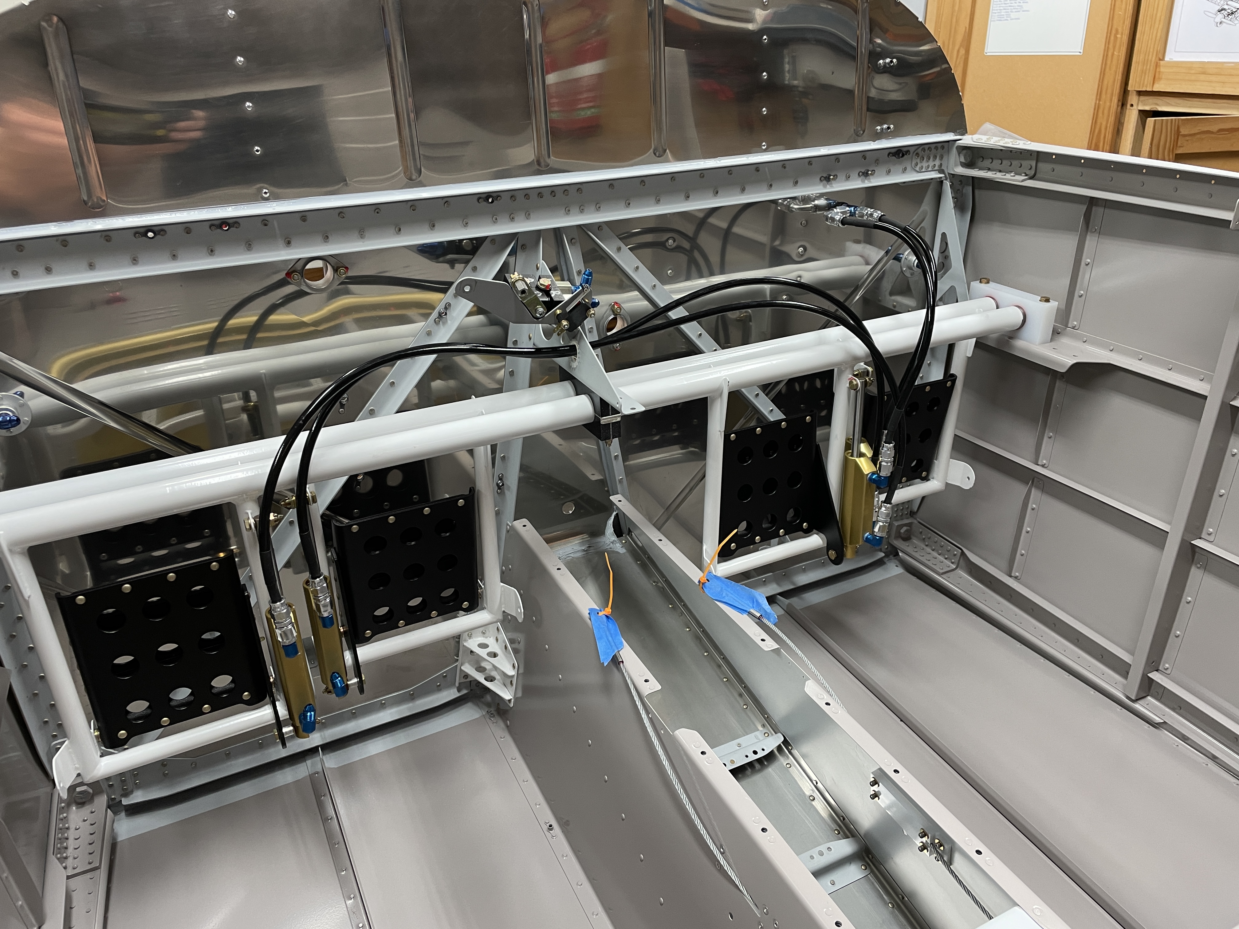
 |
| The final installation |
I made sure there was no interference, and that the pedals swung freely:
Eventually, prior to riveting on the cockpit structure above this area, i will fill the system up and pressurise it with the pedals to check there are no leaks.


No comments:
Post a Comment