Welcome to Section 26 - Lower Mid Fuse
Section 26 is a massive chapter - there are a lot of ribs etc. But when you break it down, it can be split up into sections. The first of these is the seat ribs - the ribs that are between the aft centre fuse bulkhead, and the aft fuselage bulkhead. The baggage ribs are behind this and will be the next section.
Seat Ribs Preparation
As always, i started the section by reading, reading and reading. I have found it is a good idea to read ahead through the plans first and i like to mark all jobs to be completed before primer in orange, and all jobs to be completed after primer in yellow. This breaks up the task into smaller sections and makes sure that i am not priming, only to have to countersink later etc.
Since there are so many seat ribs and there are 3 different part numbers for these, i was afraid of mixing them up. There is some logic however in Van's approach - the ribs are numbered from outboard to inboard in ascending order - There is one "15" (F-01415) on the outside, and one "16" (F-01416) first rib in on the outboard sides, and 6 x "17" (F-01417) ribs in the middle. The "17" ribs are then split into 3 pairs - 2 x 'crotch strap assemblies' and 1 x pair of 'inboard seat ribs' (the ones in the centre with the wiring 'routing angles' attached). The crotch strap assemblies have the flat sides toward each other, while the centre 'inboard seat rib' pair have their flanges facing each other.
In order not to be confused, i clecod all the ribs in their proper locations then labelled them from left to right - #1 to #10, like i did with the wings.
Then came the task of deburring everything, cleaning, etching and priming.
 |
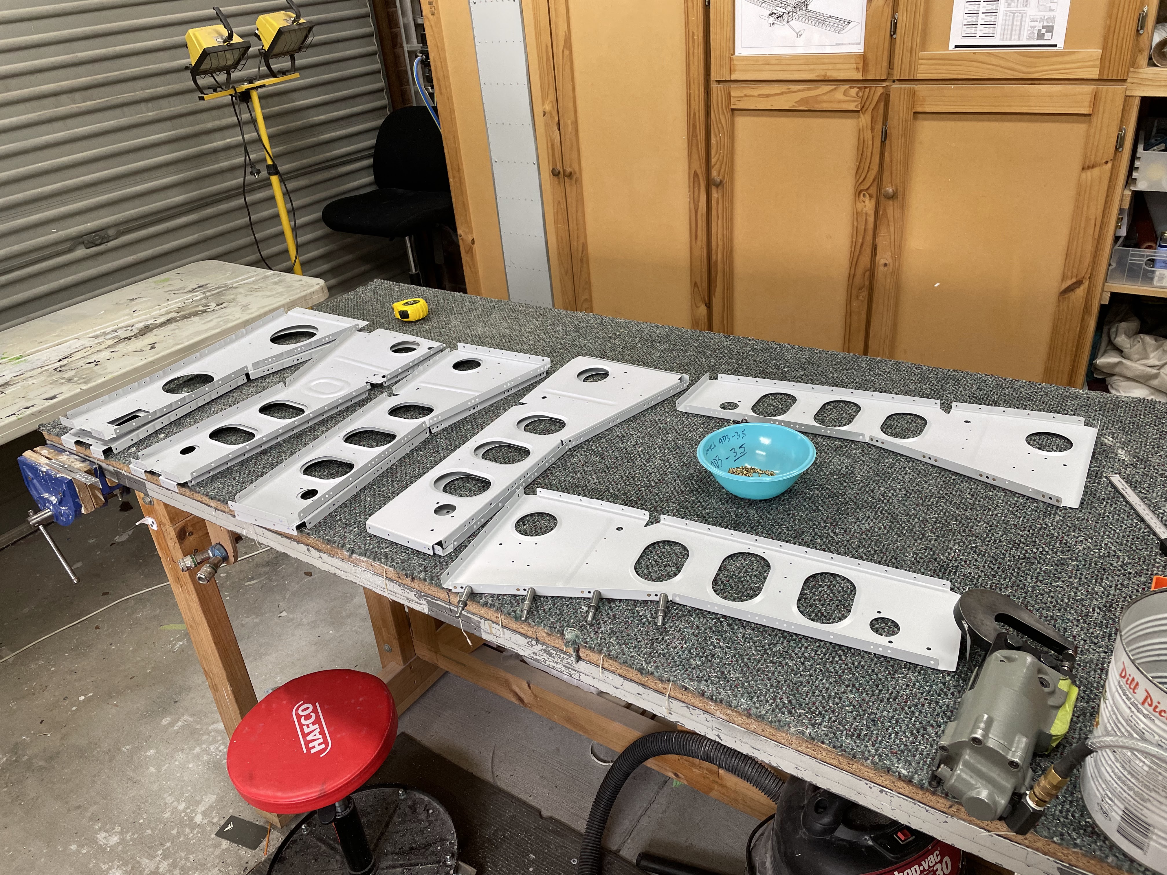
This is the pile of 'seat rib' components ready for priming.
|
 |
| During priming, so i don't lose the rib numbers, i use the same little numbered tabs i used for the wings. I then write the rib number back on, and remove the tab before dimpling and riveting etc, |
Beginning Assembly
The assembly of the seat ribs started with fluting the 2 x outboard "15" ribs into a curve, which matches the holes in the bottom skin. The outboard ribs have a good curve to them, but i just took it slowly checking all the time. The centre seat ribs were straight and did not need any fluting.
I then moved onto dimpling all the ribs and installing all the nutplates, wire routing clips and wire routing angles using the squeezer. The 'non-ramped' flanges of the 2 x 'inboard seat ribs' have nutplate holes in them. They are dimpled as per the plans, but then there are no nutplates installed. This didn't feel right to me, and i thought it would be hard later to install the nutplates - however on reading ahead, these ribs don't get nutplates now, because the nutplate rivets will be installed later and will also hold on the seat floors. #smart
I then moved onto riveting the crotch strap assemblies to the pairs of the "17" ribs.
 |
| I was unable to reach the indicated rivet with a squeezer - so i used a gun and bar very carefully. The shop head ended up being on the thinner flange of the crotch strap rib, but i didn't have a lot of choice here. They all worked out fine however, as i used a very low pressure on the gun. |
Ready to install on the spar
Now that all the seat ribs were sorted, i was able to bolt and rivet them to the spar. Once again, i clamped the spar in an upright position and used the long straight set to get to all rivets. The manufactured (cupped) head was placed on the flange of the rib (as this was the thinner material), so i ended up holding the gun upside down and in my left hand for a lot of the riveting. So long as you keep pressure on the gun toward the rivet it works well. I prefer to get it all setup, holding a good pressure on the rivet, then look at the shop head while it is setting. It's more likely, for me anyway, to slip off with the bar, rather than slip off with the long cupped set (the double offset cupped set is a whole other story though!).
 |
| Tefgel was used on all bolts, and these were torqued to 38 in/lbs once again, then torque seal applied. |
 |
| This was how i held the gun for all these rivets. |
 |
| Riveting complete. |
Riveting on the aft fuselage bulkhead
The plans on page 26-08 have you begin to work on the baggage ribs (steps 1-6), however i skipped ahead to step 8, which was to cleco on the mid fuse aft most bulkhead to the seat ribs. At this point i prepped the idler brackets and doublers, and the idler bearing, then cleaned etched and primed these, along with all the baggage ribs (see the next post!).
I clecod on the spar doubler to the centre of bulkhead angle, which will have the idler brackets attached later. The plans callout on at Figure 3 on page 26-08, Steps 10 and 11 was very confusing at first. I had to read it about 5 times - but basically you rivet the doubler, but only in the locations indicated by the 'p shaped' dotted lines - which ends up being some rivets between the bulkhead and the doubler only, and others between the doubler, the bulkhead angle and the seat ribs.
Step 11 is not asking you to rivet ALL the seat ribs to the bulkhead doubler, but only the seat ribs at the outboard edges (aka "as shown in figure 3"). When you read ahead in the plans, all the other rivets between the bulkhead angle and the seat ribs, are also common to the baggage ribs and will be riveted at that time. If you riveted them now, you could not install the baggage ribs later.
 |
| All these rivets were set with either the squeezer, or the long straight set and a bar. I put the manufactured heads on the forward side - as this way all manufactured heads were on the thinner material. |
 |
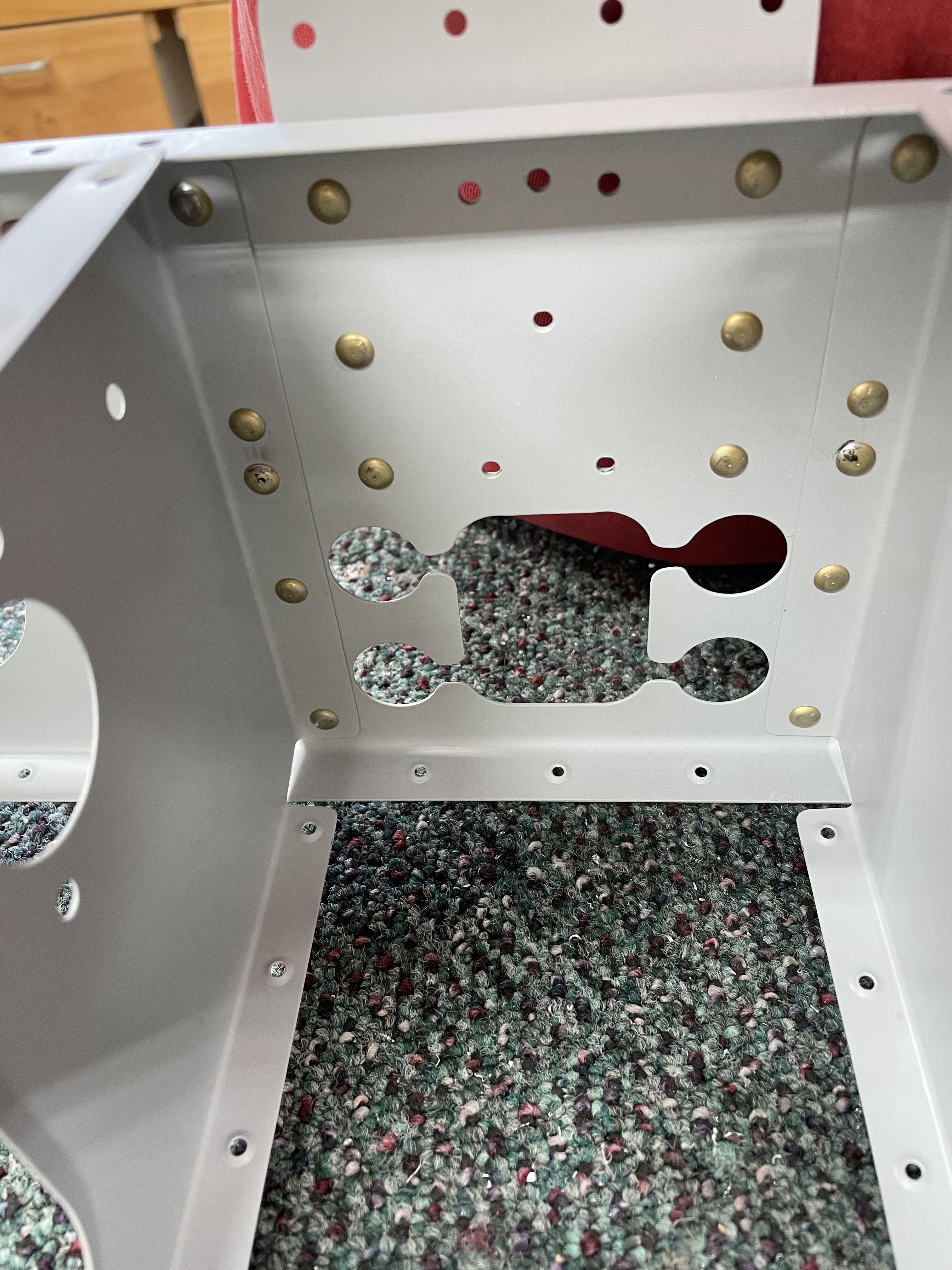
| I have not idea what the 2 holes in the centre of this assembly are for - they end up being right between the 2 idler brackets! Who knows! |
Once the doubler and aft bulkhead angle was riveted to the seat ribs, i was able to prep the idler brackets. The plans ask you to install the nutplates on the brackets first, then bend a flange into the parts. You have to do it in this order - if you bend the flange first, it would be very hard to get a squeezer into the small gap later to set the nutplate rivets. I used a hand seamer to bend the flanges, then clecod them in place and tested that the idler arms would clear the bends in the flanges - better to be sure now than have to file things later and ruin my nice priming.
 |
| The idler bearing was marked as per the plans.. 3/16 above the holes below. |
 |
| I match drilled and clecod the bearing to a piece of scrap wood for cutting on the bandsaw. |
 |
| The bracket on the right has had the flange bent, while the one on the left has not. |
 |
| I installed all the hardware needed for the idler brackets and checked they had enough clearance from the idler bracket flanges which i had just bent. |
I was then able to cleco the flanges to the spar with the bracket and bearing in place and squeeze the rivets for the bearing itself. I could then set the rivets between the idler brackets, the doubler and the bulkhead angle (spar). I had to use the gun and bar to set the rivets on the idler brackets - the manufactured head had to be forward, on the bulkhead angle, as i could not get the rivet gun on the rivets otherwise (this was as per the plans). I had to use the angled face of the bucking bar, which is a fairly rare occurrence.
 |
| Setting the rivets between the idler brackets and the bearing. |
 |
| Riveting with the shop head on the thinner material can sometimes pucker up the rib flange - i used a low pressure to make sure the flanges didn't pucker too much. |
This completes the assembly of the seat rib portion of Section 26 - next up is the baggage ribs!


No comments:
Post a Comment