Checking my building bench
The plans call for ensuring the bench is completely flat before continuing - this is for the step when you install the trailing edges. I did this by setting up a cross of builders string tightly on the bench, then lifting it up using 2 x #30 drill bits - i then checked that another #30 **just** fit underneath the sting all across the bench. My bench is a solid core fire door covered in steel, with a sacrificial yellow-tongue floor on top - where the bench was not showing up as flat, it was due to some lifting of the sacrificial top - so this was countersunk screwed to the underlying door. I also gave the bench a sand to get rid of any raised bits or glue etc.
Riveting flap skins to the substructure
Page 21-09 calls for riveting the top skin to the spars, and then to the ribs using solid rivets. The skins were clecod on and the flaps placed in their cradles. The riveting was done by placing a piece of tape and marking every 10th rivet - i then did the rivets in-between these, then in-between those etc until they were all done. The end rib rivets were done with the squeezer. I used 35 PSI on the skin to spar rivets, and 25 PSI on the skin to rib rivets. I used a mushroom set and my mini-tungsten bucking bar. I found that -3.5 length rivets were a bit short along the spar, so i used -4 length.
The plans give the following warning:
To try and achieve this, i set the flap up in the cradles and checked the angles of the flap hinge brackets - the first (left) flap needed a little bit of twisting and i was able to get it close to zero between one flap hinge and the other. I again riveted every 10th rivet etc, and between each group of rivets checked to make sure that the flap was staying true.
The trouble came with the right flap - it was showing about 0.5 of a degree out of true and no matter what i did, i was not able to remove this small amount of twist. I made a post on the forums to check if a half a degree was ok, and my TC advised me to "throw my digital level away" - it is just too accurate. A half a degree was fine - rivet on! One forum reply was that their quickbuild flaps were 3 degrees out of true and Van's advised that was fine.
 |
This is the left flap bracket pair - spot on!
|
 |
| This is the right flap bracket pair - a half a degree out. |
Riveting nose skins
Once the rivets along the spar were done, i riveted the nose skins to the ribs using MK-319-BS rivets, and solid rivets, using the squeezer for the end ribs where i could access easily. For the rivets adjacent to the flap brackets, i had to use a small piece of flap/rudder trailing edge as a wedge, in order to pull the rivet at an angle, but have the head sit flush in the dimple.
 |
| This shows the misalignment caused by the rivet gun interfering with the flap bracket |
 |
| I used a piece of the trailing edge to act as a wedge to allow these rivets to be pulled |
 |
| The wedge lets the tail of the rivet be pulled at an angle, while still setting the head flush with the skin. |
Riveting Trailing Edges
The trailing edges are completed in the same manner as the rudder. They are held in place with VHB tape to allow them to be riveted and maintain alignment. The process i used for the trailing edges was as follows:
1. I match drilled a square aluminium tube to help keep the trailing edges true, while the tape cured.
2. Cleaned the trailing edges with EkoClean, Alumiprep and then acetone. Cleaned both flap skins in the location that was left free of primer with acetone.
3. Apply the VHB tape to both sides of the trailing edge pieces and let setup for a few hours.
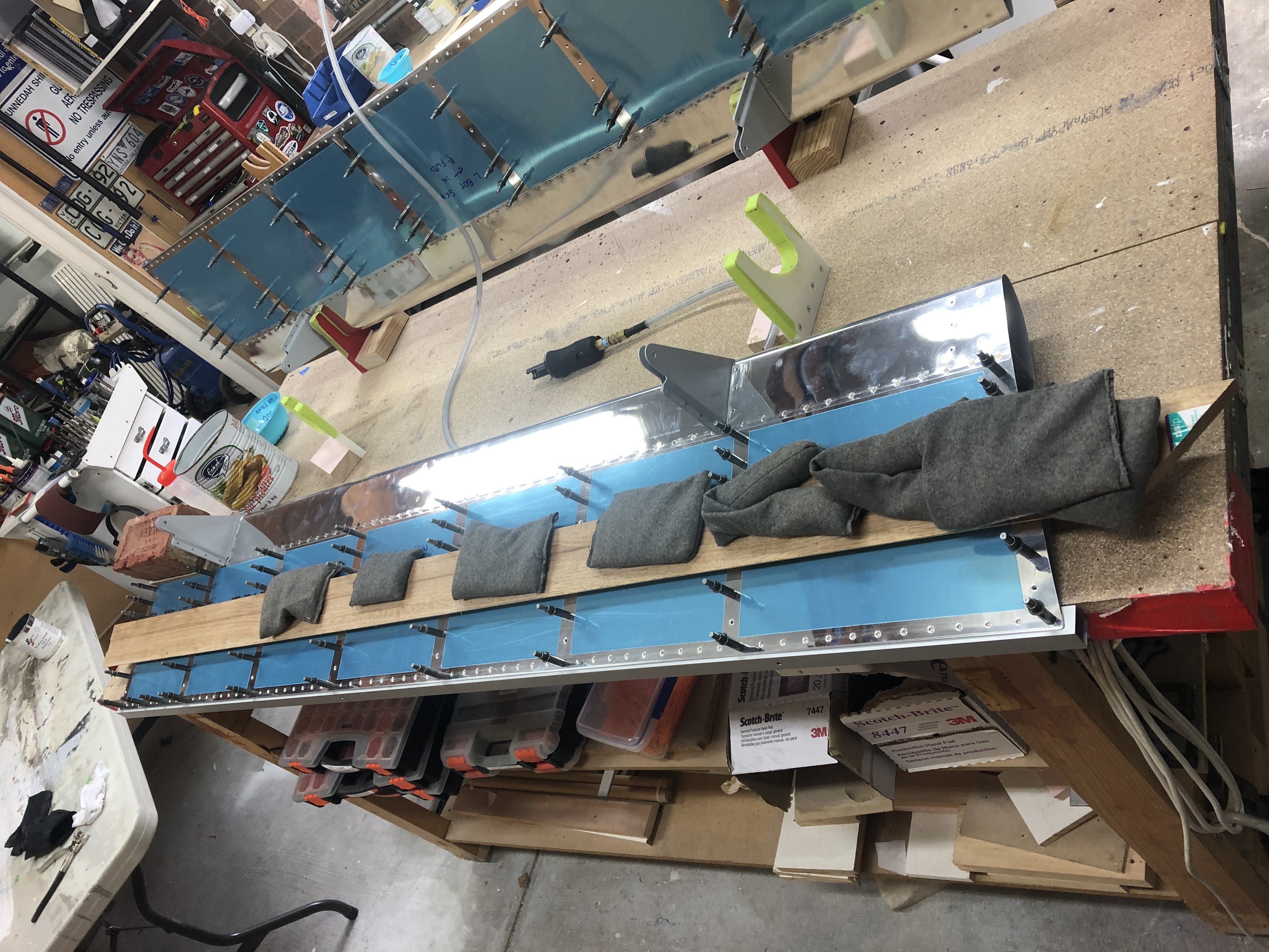
4. Weight the assembly down to the flat work bench - for the right flap (the one with the 0.5 degree twist) i used a brick on one corner and some extra shot bags on the opposite corner to make sure the flap was flat on the bench for the following steps.
5. Place the trailing edge in place and cleco with every 4-5th cleco, and cleco the assembly to the aluminium tube.
6. Peel the paper from the top side of the flap progressively from one end of the flap to the other. I remove clecos as i go, and re-cleco again in every 4-5th hole.
7. Remove clecos as required to get the bottom side tape removed, and put a cleco in every hole.
8. Let the tape cure over night. Next day, gently stand the assembly up into the cradles and remove the aluminium tube.
9. Use a cut off flat squeezer set to half-squeeze the rivets normal to the top skin surface (i.e. at an angle to the bottom skin). The cut off die meant i could squeeze the rivets a bit more and not touch the skin. The rivets were set in the middle and then one at each end. Then i did the rivets in between these rivets, then in between them - so on and so on etc.
10. Finish the rivets off with one normal die, and one die ground down to match the angle of the skins.
 |
| Prep for cleaning outside - were too long for the sink |
 |
| Here the alumiprep is doing its thang after scrubbing with scotchbrite |
 |
| This is what the prepared angles look like - a nice even dull finish from the acid etching and the scrubbing with scotchbrite |
 |
| Applying the tape to the trailing edges. |
 |
| Progressively pulling the tape on the top skin side. |
 |
| Top skin side tape removed and clecod to the tube to keep it straight |
 |
| Bottom skin side tape removed - a cleco in every hole and it gets left overnight |
 |
| Left flap weighted down to keep it flat. |
 |
Right flap with a brick on one corner and extra weight on the other - to help hold the small amount of twist out.
|
 |
| Here a rivet has been partially set - the die on the right of the photo has had one side ground down so it clears the skin. The squeezer is adjusted to allow for the maximum squeeze with the die barely a hair above the skin surface. I drew a mark on the aft side to make sure it didn't rotate. |
 |
| This is what the partially set rivets look like. |
 |
| This is the set used for the final squeeze - one die has been ground down to match the angle of the skins. These were the ones i used on the rudder. They look deceptively close here - but as they squeeze the yoke pulls apart a little - I adjusted the set so it touched the skin with the ram extended and it needed a few more turns to get it right. |
 |
| Here the dies have just final squeezed a dimple. If i dropped the dies lower down the skins they would damage the skin - so the gap between the dies was set by aligning the top of the die with the trailing edge. This was done on every rivet to ensure the dies were in the same spot for each rivet. I like using the squeezer as you know every rivet is set the same amount (same tension). I think it is less likely for a trailing edge to bow. |
 |
| The end rivet has been final squeezed flush into the dimple, but the one next to it is still half squeezed. |
 |
Final squeezed rivets. They don't fill the whole dimple, but they are flush with the skin.
|
Finishing up
To finish up the flaps, the holes on the bottom skins were drilled to #33 and MK-319-BS rivets installed. The end ribs were done with a squeezer. Every time i use these rivets i think what a pleasure a RV-12 must be to build!
The flap extension rod end was installed and torqued - for an AN4 bolt in a nylock nut the tables called for 85in/lbs and i measured the running torque of the locknut at 25 in/lbs, so used 110 in/lbs total. I used torque seal to mark the bolt.
Finally - the flaps were installed on the wings!


No comments:
Post a Comment