The MEGA FIBREGLASS POST!
The fibreglass fairings have been a real learning experience. The process has developed troughout the section, with me learning along the way. It seems to take an inordinate amount of time due to always having to wait for the part to cure before you can work on it again. This post therefore will be a summary of the process as a whole, to try and document the general idea on how the fibreglass tips were completed, rather than detailing each individual part.
Installation and Rough Shaping
I began by squaring up the transition from the part to the flange (as per plans page 12-02) - these were curved and would not allow the part to be pushed in as far as it needed to be. Once this was done, i could roughly fit the part and trim the flange to the dimension shown on page 12-02. At this point, i also sanded off all of the raised seams where the parts were joined together by the factory.
 |
| You can see the seam on the left part which needs to be removed |
 |
| The part is bowing away from the skin in the middle |
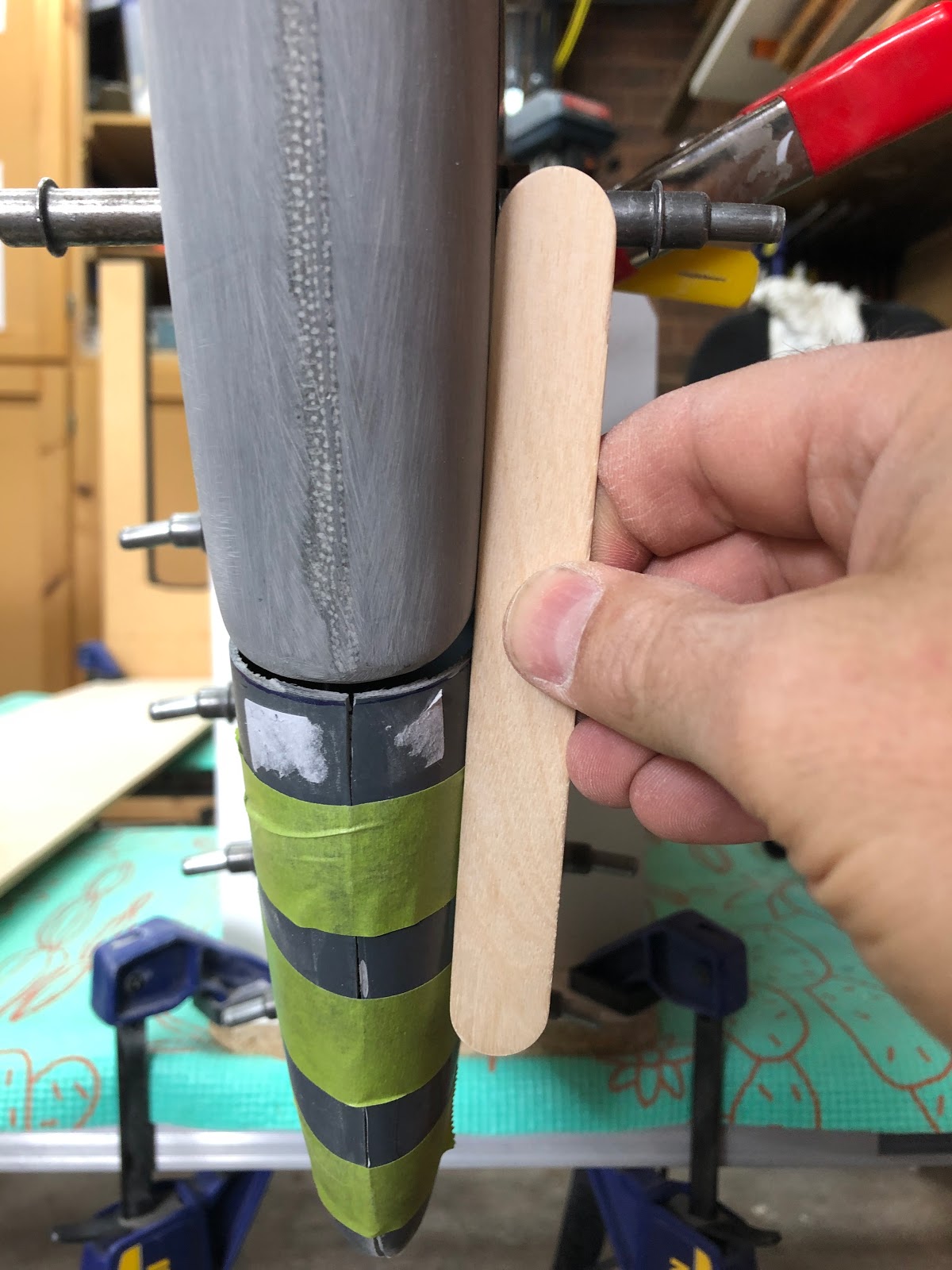
Once at this point, the part is able to be roughly fitted into place. However, in most cases the part bowes inward away from the holes, making match drilling fairly hard. In order to allow the part to be match drilled, i used either wooden "tongue depressor" sticks, or shaped foam blocks to push the flanges apart. An example is shown here from one of the HS tips.
 |
| The part is rough cut oversize, to allow it to roughly fit. |
 |
| A foam block is cut which pushes outward on the flanges and allows it to sit tight under the aluminium skin. |
 |
| Whatever is needed is used to hold the part in shape. |
It was important when doing this is make sure that the part was not pushed outward too much, changing the shape of the part so it did not 'flow' nicely with the curves of the surface it was attached to. Here i am checking the HS tip is not bowed up too much.
 |
| This is the VS to rudder tip transition - a wedge had to be cut out of the middle to allow it to fit more nicely. |
Once this is done, you can hold the part in place and match drill #40 all of the attach holes. I started at the front and worked my way to the back for each part. Once this was done, i was able to sand into the gelcoat / fibreglass to very roughly fix the shape of the part, so that it matched the surface it was attached to. This will be corrected later with epoxy and micro.
 |
| The spots are where the thickness of the part needed to be reduced in order to 'flow' nicely with the surface. |
All trailing edges were sanded to be flush and square at this point - if they are short it can be fixed with micro later.
In some cases the part is not the right shape at all - the VS tip for instance was a lot thicker at the top than the bottom and made for a weirdly shaped VS compared to the rudder. This dimension was reduced by cutting a wedge out of the part, clamping back together and applying flox / cloth over the area to glue it back together (more on flox later)...
 |
| A wedge was cut out of the VS tip to reduce it's diameter |
The final task before moving on is to sand off the square edge where the fibreglass buts up against the aluminum skin (as per Section 5). You want to leave a rough sanded area that the micro will stick to, that is lower than the skin, so there is room for the micro so have some depth and to adhere properly.
Closing the gap
Where a part has an open end, such as the HS tips or the VS tip, a layup of 3 layers of 10oz cloth is made. The middle layer is cut at a 45 degree angle. The cloth will be laid up on a aluminium form, which shaped as per the part you need, then waxed so the layup doesn't stick.
 |
| This is the radius of a circle from the rudder hinge to the counterbalance arm... |
 |
| Under the layup is a bent aluminium form that has been waxed. |
The process begins by mixing some epoxy. The amount is worked out using an online resin / cloth ratio calculator. Once the cloth is cut to roughly the correct size, i weigh the cloth then use this weight to work out the proper resin ratio. I then get 2 pieces of "builders plastic" and cut it larger than the aluminium form. I trace the shape of the final component onto the back side of the sheet of plastic to give me an idea of how large the piece needs to be saturated. All the components are laid out on the bench and the first piece of cloth is put on top of one of the pieces of plastic. Around half of the resin is then poured on. I use a hotel card to spread it out and work it into the fabric, making the fabric go transparent.

Once this layup is complete, one side of the plastic is removed and it is placed onto the aluminium form I waxed earlier. A roller is used to make sure it is pushed down against the form. The top piece of plastic is then removed, and a piece of peel ply is placed on top and it is rolled again, and left to cure.
 |
| Before plastic peeling and being placed onto the form |
 |
| Rolling with the top piece of plastic still on |
 |
| A piece of peel ply finishes off the sanwich. |
The result is a shaped piece of fibreglass ready to glue in and close the gap in the fairing.
To actually fill the gap in the fairing, I place the fairing into position on the aircraft, the trim the piece of fibreglass we just laid up to fit. Once it is in place, it is held with tape or some other method, then tacked in position from the outside using superglue.
 |
| Trimmed piece (and the template i used to trim it). |
 |
| Once in position, it is tacked in place with superglue. |
Next i begin by prepping all my materials and mixing up some epoxy. A small amount is poured off into a seperate cup, then the remaining bulk of epoxy has "flox" - or flocked cotton fibre mixed in with it. The consistency needs to be similar to the "dry micro" in that the flox mixture will not sag or run. This is then applied using a 'tongue depressor' as per the plans into the corners of the part and the tacked on piece of fibreglass.
 |
| Flox applied into the corners |
Befor the flox has time to cure, a piece of fibreglass cloth needs to be placed over the flox and about 1" up the sides of the part. To this this i do one of two things - i either wet out a piece of fibreglass cloth on a piece of plastic, put another piece of plastic on top, cut to shape, peel off the plastic on both sides and lay it into the part...
 |
| Cloth wetted out on top of a piece of plastic. |
 |
| Being cut to shape with a 2ns bit of plastic on top |
 |
| Finally laid into the part. |
The other method (suitable for smaller pieces of cloth) is to brush in some neat epoxy, then lay the pieces of fibreglass into the part on the wet epoxy and flox, then wet it all out with a brush.
Once the fibreglass patch pieces have all cured, the outside flange can be cut off with a bansaw, then a vixen file works really well for taking the edges back flush to the part.
Support for the pull rivets
I plan on riveting the tip on, rather than glassing them as some people do. I was concerned that the pull rivets would 'pull through' the soft fireglass over time, so i planned on installing some aluminium strips to give them a bearing surface. Since the fasteners will be #30 size, the stips needed to be 1/2" wide. These were cut from 0.025" thick scrap, then shaped, deburred, match drilled, and primed on one side only. They were glued on using epoxy with a little bit of flox (flocked cotton) mixed in to provide strength and also give some thickness to fill the voids in the rough fibreglass surface i was sticking them to.
Icing the cake and fine tuning the shape
Once the parts are installed and match drilled, they are sanded all over with 60 grit to give a nice rough surface for the next step. The edges of the aluminium structure have electrical tape applied to stop any epoxy sticking to them - you don't want to glue the tips on! I like to apply one layer of tape on the edge and but it up to the line of holes, then fold it over the edge, then a second piece of tape butted along the other side of the holes against the first bit of tape, to give a bit more protection from sanding the aluminmum.
Once the aluminium is taped up, the part is installed with clecos again. I get out all items needed for the next step, so i don't have to go searching. I then mix up some epoxy and mix in some "miccrobaloons", which are tiny glass balls. These thicken the epoxy and provide a strong matrix once cured which is easy to sand. You are looking for a "dry micro" consistency - which is where it will not drip off the mixing stick. I take it out of the container, and onto a plastic plate to stop it exothermically going off so quickly.
 |
| A batch of "dry micro" aka icing mixture |
I find the best tool for the next step is to use an old "hotel card" (door key). Basically, i apply micro all over the part, with a thickness that allows me to achieve the shape i want to achieve. It is applied over the part to aluminium skin transistion (onto the tape), to allow you to sand it back later and get a very nice edge.
 |
| The HS has packing tape applied near the elevator tip, and electrical tape near the HS tip. The electrical tape is much better in that is much easier to remove. |
 |
| Here the micro was applied fairly thickly at the top, so that i can sand it back later and end up with the correct shape to the parts. |

Getting in shape
I let the "dry micro" mix cure for around 24 hours, and then it was time to attain the shape i was after. On one part it had to be left for a week - even then the micro was easier enough to sand off. The process for removing the micro starts with a 'surform' file, which literally 'cheese grates' off the micro. Go easy with this though as it is very aggressive. I then use a permagrit sanding bar (long 12" one) to shape the micro to the desired shape. When i got close i switched to 60 grit sandpaper - always using a sanding block so as not to create an uneven surface. This was also used to gently sand back the micro down to the tape and get a flush transition to the skin.
 |
| This is the 'surform' file - aka cheese grater. |
 |
| It makes a lot of cheese! |
This is how the parts look once they were sanded to shape. You can see how the micro made a nice flush transition to the skin, and where it was used to correct the shape of the parts. There are some voids left by air bubbles in the micro, and also lots and lots if tiny pinholes where the glass bubbles have been sanded open.
 |
| Voids caused by air bubbles |
 |
| Pinhole city. |
Finishing - the first step
The large voids and the pinholes all need to be filled - before the next step. To do this i mix up a filler using epoxy the West System "Microlight" filler (beige color). This is a lot finer than microballons (almost like a powder) and fills all the small voids very well. This is applied with a hotel card, but not thick at all - just enough to fill the voids. Once it was cured, it was sanded off again with 60 grit on the long sanding bar.
 |
| After the "microlight" was applied... |
 |
| ...and after being sanded off again. |
At this point all the large holes and voids have been filled and its time for the next step.
Finishing - Step 2 - the skim coat.
Next up i used a roller to apply neat mixed epoxy to the surface of the part - 'neat' meaning it was mixed but had no fillers mixed into it. I rolled on a coat, then used a squeegie to take it all off again. I let this sit for about an hour until it was tacky, then rolled on another coat (but did not squeegie the 2nd coat off). Once this was dry, i was able to very gently sand the part to a smooth finish. This efectively filled 100% of the pinholes in the part in one step.
 |
| The roller i used - next time i will use a foam one so hairs don't fall off. |
 |
| Pour the epoxy out onto a plate or... |
 |
| ...it exothermically reacts and sets super quickly! |
 |
| Here are the parts after the epoxy was applied |
 |
| The epoxy skim coat was sanded back very gently to a smooth flat surface. |
Finishing - the almost* final step
The almost final step is to coat the parts in your favourite high build primer, to fill any final sanding scrathces and to get a final good surface for painting. In my case i used a waterbased 2 part epoxy primer called "Aquacote" and brushed it on. Next time i will use a foam roller to apply it. Once it is cured, it was dry sanded with the permagrit bar, then 60 grit and 80 grit on a sanding block. Then wet sanded with 180, then 400. The result was a very smooth shiny surface, ready for paint.
*Almost: I say almost, because there are a few tiny tiny imperfections which need a small amount of filler before the final primer coat is applied, but nothing too bad. Mabe 3-4 little divots on all the empennage fairings.
 |
| Wet sanding the high-build primer with 400 grit |
 |
| Elevator and HS fairings all done - ready for a lighy coat of primer before paint. |
A final note...
One final note is on the epoxy skim coating step - at the time of writing of this post, the rudder top fairing and the VS fairing are still at the dry-micro sanding stage. I am toying with the idea of skipping straight from the microlight filler step, to the high-build primer step. This is because this particular high build primer is almost as hard as epoxy, and i think i should be able to sand it back to fair without needing the epoxy skim coat underneath. Will report back soon!


No comments:
Post a Comment