The VS parts are all prepped, and i'm waiting for a delivery of Stewart Systems products, so i started on the rudder preparation.
7-02 Step 1-5 were completed with no issues. The stiffners took a while!
 |
| R-405PD rudder horn is rounded to allow it to nest into the R-00904A bottom rib |
 |
| The R-00914A bottom rib cutout interfered with the hole in the R-405PD rudder horn, so i opened this up a bit. |
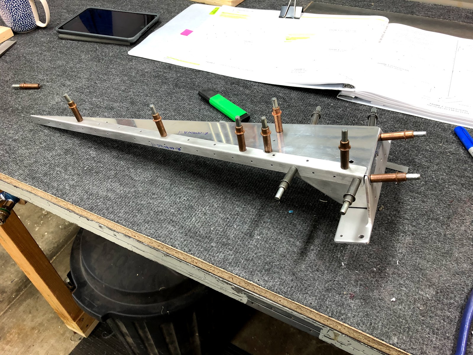
7-03 Steps 1-3 were completed up to ready to disassemble and deburr all parts. I decided to cleco all the parts together to see how the fit was, and noticed that one of the holes that takes a LP4-3 rivet, to connect the R-00914A and R00914B bottom ribs together, may have an interference problem with the R-00910 rudder horn brace:
 |
| Lower rudder assembly cleco'd together |
 |
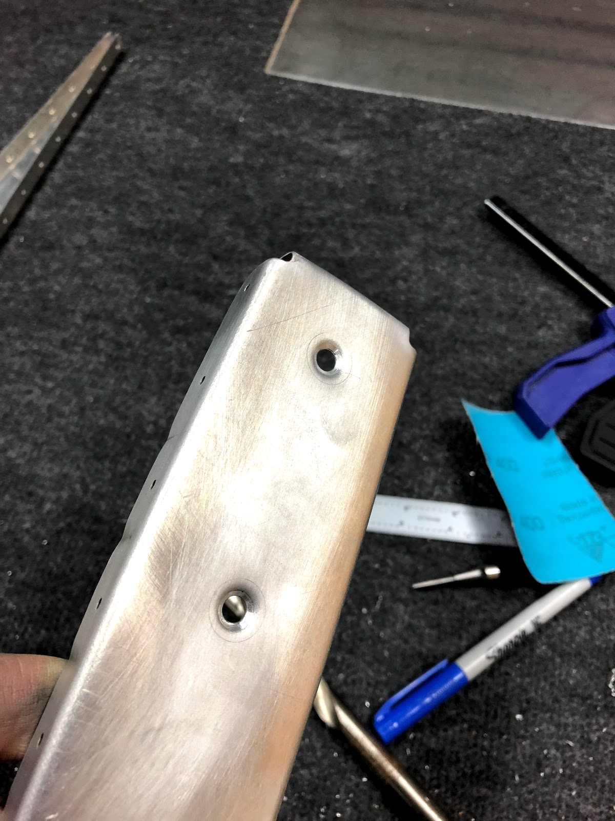
| Hole which needs to take a LP4-3 rivet may interfere with the R-00910 rudder horn brace |
 |
| Hole which needs to take a LP4-3 rivet may interfere with the R-00910 rudder horn brace |
 |
| Hole which needs to take a LP4-3 rivet may interfere with the R-00910 rudder horn brace |
It seems this is a common problem, and a few builders have found the rivet just fits -
(VAF Discussion here). I must remember before i prime, to cut the mandrel off a rivet and put it in the hole to check for interference.
Moving onto 7-03 Step 3, I made my first error of the project!
Referring to 7-03 Step 4, my assumption was that the counterbalance and top rib image was shown with the ribs laid flat (as you see in other sections of the plan). I therefore assumed that the ends of the ribs needed to be radiused. I fitted the ribs to the skin, and could not see why i would need to cut the ends of the ribs, but figuring the plans knew something i did, i forged ahead and radiused the ribs as below:
 |
| Looks about right? |
I then went back, but the overlapping skins STILL didn't fit well, then i realised that i had read the plans wrong! DOH. They meant to radius the edges as if you are looking from above:
 |
| Should be radiused in this plane, to assist the skins in folding around the corner. |
Luckily, i was diligent with the edge distance, and made sure i had 3/16" of edge distance around the front hole, so just may have dodged a bullet. I have never seen anyone else make this mistake, so i must be special!
MOVING ON!
Page 7-04 was completed in it's entirety, which was basically preparing the edges of the skin. The holes in the middle of the skin i left alone, as i need to deburr some when i match drill the ribs later, and i will run a scotchbrite over the other holes at the same time.
My edge prep is speeding up. Today it went something like this:
1. Left all the blue on the skins, right to the edges.
2. Vixen File to remove the steps
3. Smooth file to remove any teeth marks from the Vixen
4. Edge Deburring Tool
5. 400 grit sandpaper.
Regarding the blue film removal: I stated to use a soldering iron on one side as i did on the practice kits, and it was tedious and not really worth the time i don't think. From now on i think i will just try and do all the edge deburring, drilling etc with the blue film on, then once the film comes off i can deburr the holes and it should be ready for prep.
The random couple of holes at the tops of the skins were dimpled.
 |
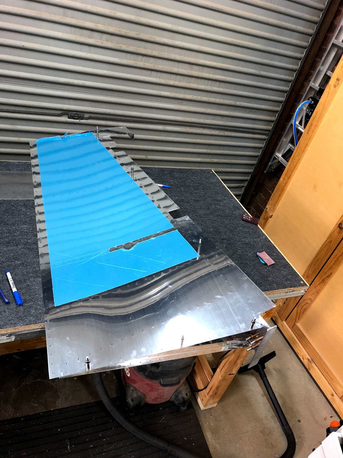
| Skin cleco'd to the structure to check fit around the rudder horn |
The skin was then cleco'd to the skeleton, in order to check fit of the skin around the rudder horn. I found both sides needed to be relieved a small amount (1/16" ish).
 |
| Before relieving... |
 |
| After relieving a little. |
Once this was done, the top ribs were cleco'd to the spar, and 7-04 Step 7-8 called to final drill the rib to spar attach holes. I hate match drilling when there is only one cleco left, as you never know if the rib will move and there didn't seem any way to clamp it in place. So i attached the left skin, and used this to keep the ribs in place while i match drilled one hole at a time. Removed and deburred those holes.
 |
| Since it was together and looking like part of an aircraft.. |
Finally, i worked on the lead counterweight. I was leery of dimpling such large holes (#12) so made up a token of 0.032" skin and did some practice ones (which were also used to check the CSK on the lead weight itself).
 |
| These are some big dimples! |
Once this was done, i final drilled one hole, then match drilled the other by marking a centreline between the tooling holes, putting a screw in the hole and clamping the lead to the bench. Match drilled, then removed the lead and deburred very thoroughly. I was then able to dimple both holes in the rib itself. I did lightly run the countersink deburring tool into the dimples to help the fit of the screw. The lead weight was countersunk with the deburring tool only by eye and test fitting the dimple token.
 |
| Bottom. |
 |
| Top |
 |
| With the AN509-10 screws in. |
Next up is page 7-05, but this requires riveting the bottom rib and reinforcement plates to the spar, but i still don't have any paint. So i am going to skip this page, and move onto 7-06 and 7-07 where i assemble to skeleton and skins and match drill the skins and trailing edge.


No comments:
Post a Comment