Next up in Chapter 29 (and nearing the end!) was to complete the root fairing angles and the seat brace.
The root fairing angles are the little curved angles which are installed on the fuselage for the wing root gap fairing to screw into. The seat brace is the athwartships brace which the seat backs will rest against, and has some beefy structure to join the roll bar onto the side longerons and the rest of the fuselage.
Parts Prep
As usual, work starts with preparing the parts. The plans asked me to drill the screw holes for each nutplate to #17. However, i did not own a #17 drill. When referencing the future sections, these get -08 sized nutplates, and the screw callout is for #8 screws. So i drilled them to #19, as this is the normal size i use for a #8 screw. If the screws don't go in later (for some strange reason), then i can buy a #17 and drill them out a bit.
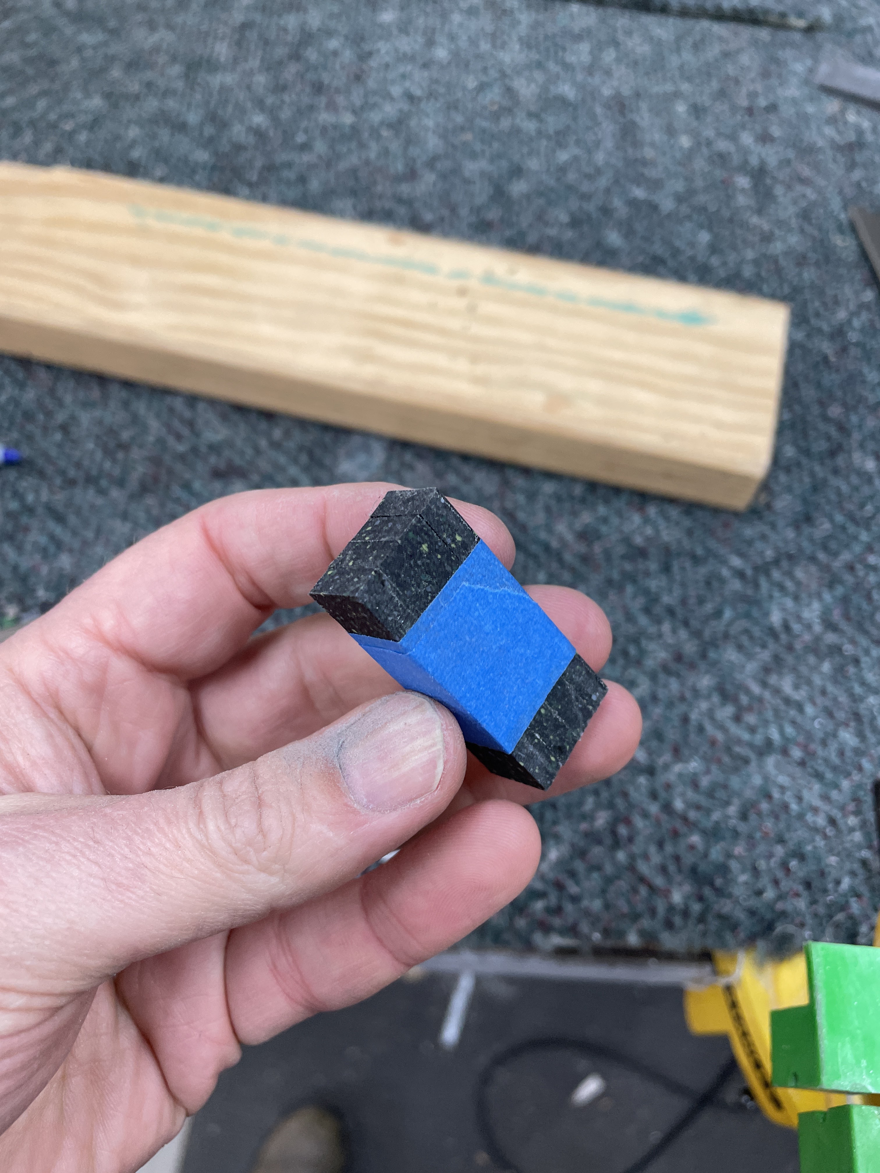
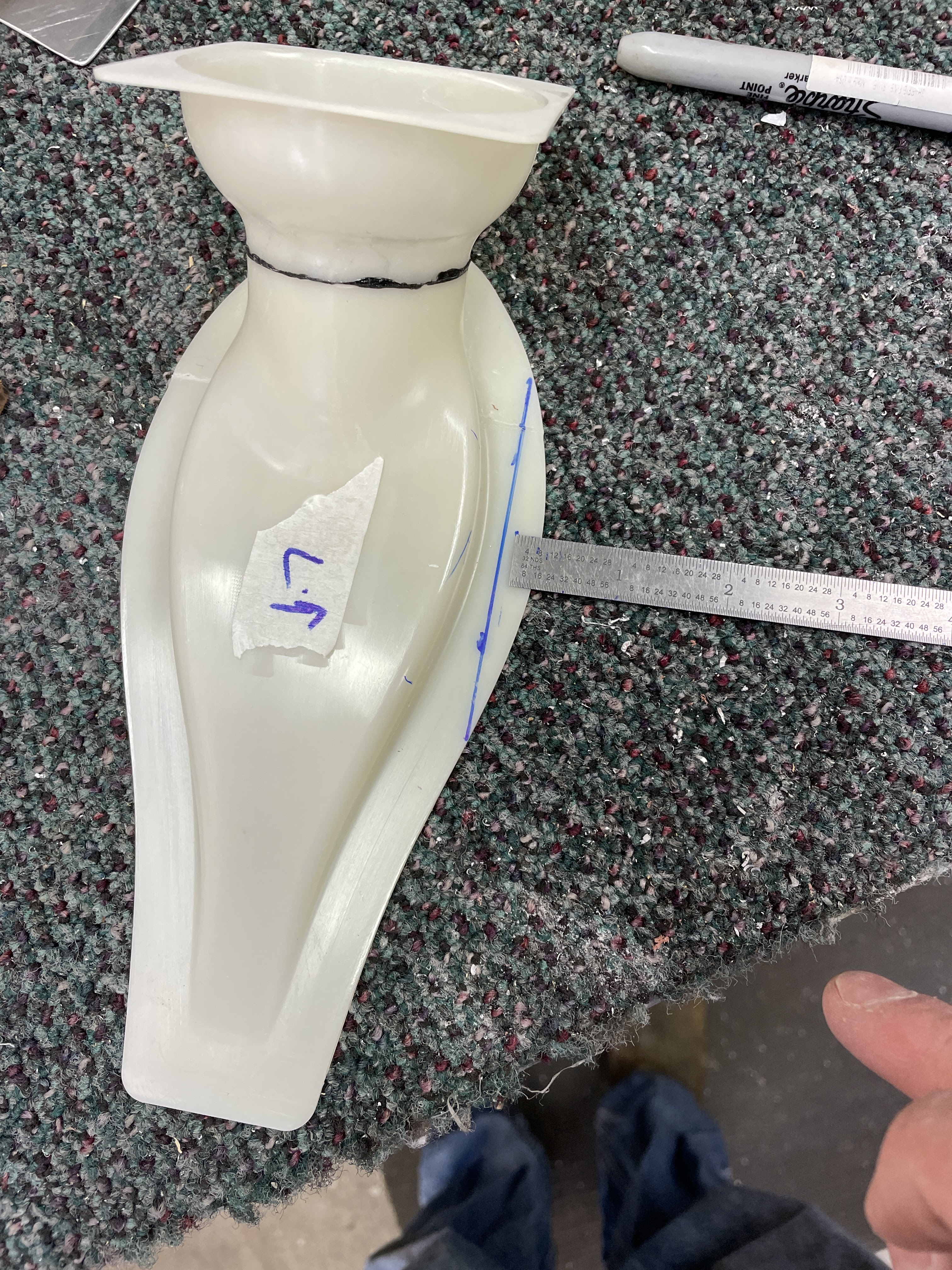
Next up i cut up some plastic stock, and prepared the seat back guides.
 |
| I found this plastic stuff (whatever it is) didn't file very well - but was an easy task to shape it on the grinder (not the scotchbrite wheel, but a normal wheel for steel which comes on the grinder). |
 |
| The parts were all trimmed as a bunch. |
Next up the countersinking tool was taken out, for some countersinking on the seat back brace and the plastic seat back guides.
 |
| The shim was countersunk in-situ to provide support for the countersink pilot |
 |
| The seat guides were also countersunk in-situ for the same reason. |
Next up was to cleco on the roll bar gussets and match drill these to the airframe.
 |
| Deburring inside the longeron was a challenge! |
Air Vents
Next i clecod on the parts which will form the panel, and positioned and clamped the air vents into position. This then allowed me to match drill and trim the vent pieces and these will need to also be primed. I masked off the areas where the vents will glue to the fuselage and these areas were not primed. I will need to eventually remove the primer at the location where the vents will attach. I will do this before cockpit painting.
 |
| I sanded the flanges flat on the backrivet plate. |
 |
| Neodymium magnets hold the vent in place. |
 |
| This was how i marked the top of the vents for trimming.. |
 |
| ...and cross checked this with the plans dimension. |
 |
| Vents match drilled and trimmed to shape. |
Once primed, air vents will be put aside and installed in Chapter 35 once the panel structure is in place. All remaining parts for Chapter 29 were cleaned, etched and primed.
Root Fairing Angles
Next up was to flute the root fairing attach angles to match the curve of the side skins. The plans give some locations for this dimpling and i found it to be almost spot on. Nutplates were then riveted to the root fairing angles, however were left off in locations where they would interfere with riveting the angles to the fuselage later. Nutplates were also installed on the lower skins. Once riveted to the side skins, the remaining nutplates were installed.
 |
| Dimpling was done with the hand squeezer, as the compressor shit the bed and i had to rebuild the head. |
 |
| Before fluting. |
 |
| These were the recommended fluting locations as per the plans - the digital plans show the image in colour, which is easier to read in some cases. |
 |
| I marked these with a chalk pencil and then fluted in these locations. |
 |
| Initial fluting was a little too much, but i was able to flatten some of them with a hand squeezer. |
Next up the root fairing angles were riveted to the fuselage sides, along with some web stiffners on the main spar carry-through webs.
 |
| Hefty web stiffners. |
 |
| Nutplates installed on the lower skins |
 |
| There was even a nutplate between the spars - the pneumatic squeezer just fit. |
 |
| Some of the root fairing rivet tails were totally hidden under the skin stiffners, and i had to use a mirror to see what i was doing. |
 |
| I also had to get pretty creative with the bucking bar for the lower root fairing angles forward of the spars. |
Next up was to re-install the aft wing spar attachment bars. Back on Page 25-02 in Chapter 25, the hardware callout for the aft attach bars asked for MS21083 nuts. These are 'low height' or 'shear' nuts. They are not designed to hold a part in tension, only to really hold the bolts in place to provide the shear capacity of the joint. As such the torque values in Section 5 of the plans did not apply - i had to use my engineers handbook to look up the correct torque for these nuts. The running torque was 10 in/lbs (surprisingly low for a -5 sized nut), and the book value torque was 60-85 in/lbs, so i torqued them to 95 in/lbs.
Seat Back Guides
Next up i riveted some nutplates to the seat back guides (doh!) then riveted the seat back guides to the seat brace bar. I did not install any of the plastic components at this time, as i will be final painting the cockpit. These can all be installed once the painting is completed. I was then able to rivet the seat brace to the fuselage - i was able to reach the inboard 2 rows of rivets with the squeezer, and used the gun and bar on the outboard row of rivets.
 |
| Houston? We have a problem here. |
 |
| I could reach the inboard 2 rows with the squeezer, but not the outboard most row. |
 |
| The remaining 2 rivet holes on each side were done with the gun and bar. |
I was then able to complete the riveting of the remaining components, with some creative uses of the bucking bars!
 |
| I had to squeeze the bucking bar into position, and use some thin masonite as a lever to keep it up against the rivet tail. |
 |
| Some of the rivets were tricky but doable. |
 |
| The tungsten bar was able to reach these rivets, but not the outboard most one, as it hit the longeron. |
 |
| Even this old thing was taken out as it was the only one which would reach around the longeron, onto the outboard most rivet. |
 |
| The intercostal was then bolted into position and riveted. |
 |
| Getting these nuts on was also tricky. |
 |
| The lower intercostal rivets did themselves! How handy. |
So that basically completed Chapter 29, with the air vents parts being deferred until later - a very long chapter! It ended up being 81.5 hours of work, and 1,668 rivets!
Next up - Joining the tailcone to the fuselage!!!


No comments:
Post a Comment