The rear baffle was a fairly monumental task in the tank build - it means it will be the last time to look inside and fix any issues with my work so far. Once it is sealed up, it means crossing your fingers and hoping it doesn't leak!
Water Test?
A lot of builders before me have filled their tanks with water before the baffle is installed to test to see if there are any major leaks - in consultation with my TC, we decided not to do this on my tanks. He reckons that my workmanship is fine and it is unlikely i will have a leak, however the main reason is that water is larger than fuel - so it would only show up a major leak anyway. Not worth the time and effort.
P-P-P-P-P-B-L-T
Prior Preparation Prevents Piss Poor Baffles & Leaky Tanks!
I reckon i looked at 20 blogs on how people did this and also watched Van's new video a dozen times. I made up a plan of action for each step to take, however instead of listing the process here i will just show you what i did.
The day prior i installed the baffle and Z brackets and made sure a rivet could be inserted into each and every hole. The Z brackets were reamed to #30 as a lot of the holes were very marginally misaligned and a rivet would not pop in easily.
Once this was done I worked out how i was going to attack each rivet and what tool i would use - time is short when you have sealant mixed (even B2 sealant)!
 |
| Tools laid out |
From left to right:
- Clecos ready to go
- Gun and Bar was to be used on the 2 end Z-Bracket solid rivets. There was no way the squeezer was going to fit. I used 60 PSI and the tungsten bar shown fit all the rivets in a number of different orientations
- Squeezer was setup for the flush rivets along the baffle flange to skin junction. I ground down a flat set in the corner so it didn't interfere with the inside radius of the baffle flange.
- The hand pull-rivet gun was used on all the baffle to rib flange rivets - the pneumatic one did not fit.
 |
| One squeezer die was ground down to cleat the flange radius of the baffle. |
I started with the LEFT tank:
 |
| Tank was completely cleaned out with ISO then blown out to make 100% sure there were not contaminants. |
For the record, here is the proof i didn't leave a vacuum cleaner or honey badger inside:
 |
| Z brackets cleaned and ready to go |
 |
| Baffle cleaned and ready to go - the taped off areas around the Z-Brackets was unnecessary. |
 |
| These are the mix of rivets ready to go - after being soaked in acetone |
 |
| Sealant measuring and mixing items ready to go |
 |
| I did the maths and used 1.3g per inch of baffle and ribs - for a total of 104 grams of Part A sealant. This ended up being a little bit too much. |
The sealant was applied in the following order - for the rib and baffle flanges i just put it on with a stick - this is a much slower process than using the syringe but results in a much thinner smear of sealant. This is important and is warned against in the Van's video - you don't want too much lest you dimensionally change the tank and it will not fit properly.
 |
| Each rivet hole in each rib flange was surrounded by sealant - sealant along the whole flange was not necessary. The end rib flanges were covered in an even coating of sealant along the whole flange. |
 |
| The baffle flanges were covered - i used the tins to place the baffle on as you can't easily hold it whilst applying sealant |
 |
| A 3/16" maximum bead was laid down on the TOP skin first, then left to sit for a few minutes while... |
 |
| ...sealant was applied to each z bracket (thinly) |
 |
| Then a bead was also applied to the BOTTOM skin. I placed the tank on the bench to do these beads. This was then left for 3-4 minutes to help prevent it sagging. |
 |
| The tank was then placed in the cradles again and a bead placed along the inside edge of the end rib flanges. A large glob was placed in the corner |
Once the end beads were done, i was quick to grab the baffle and was able to slide it down past the large screw dimples in the skin at an angle, so as not to scrape of any sealant from the baffle flanges. The baffle was pushed into place. I clecod the skin to baffle holes first, then once this was done, clecod the Z brackets into place.
I did not get any photos of the actual riveting process, as this was a time sensitive task and to be honest i got in the groove. However, i followed the following process to set these rivets:
- Set the pull rivets along the baffle to rib holes (2 per rib). The rivets were swirled in sealant before being put into the holes.
- Set the pull rivets along the Z brackets. For each one i used 3 clecos, so pulled 3 rivets, removed the clecos then pulled the last 3.
- Set the solid rivets along each end rib using the gun and bucking bar set to 60psi. These all went fine although the PSI may have been a little bit high.
- Once these were done, i used the sealant left in the syringe to fill in the upper corners on the outside where the rib and baffle meet - this is a common leak point and i wanted to get to this before the sealant went off. I was at the 1:30 mark already at this point (the application of sealant takes ages).
- I had clecod every un-countersunk hole in the skin, and also every other 3rd hole. So i carefully cleaned out each countersink of sealant, then added a rivet to each open hole, then went along with the squeezer and set all these rivets. I had to wipe the squeezer die frequently.
- Finally, i removed the last of the clecos from the skin to baffle which were in countersunk holes, cleaned these, added rivets and set them also with the squeezer.
 |
| Twirling the pull rivets in sealant as per the technique recommended in the Van's video |
And here is the finished result after some clean-up of stray sealant:
 |
| Sealant was added into the corner here as a backup to the glob placed inside the corner of the tank |
 |
| These were set with the gun and bar |
 |
| These were set with the rivet puller |
 |
| Outboard end corner sealant. |
 |
| The completed baffle |
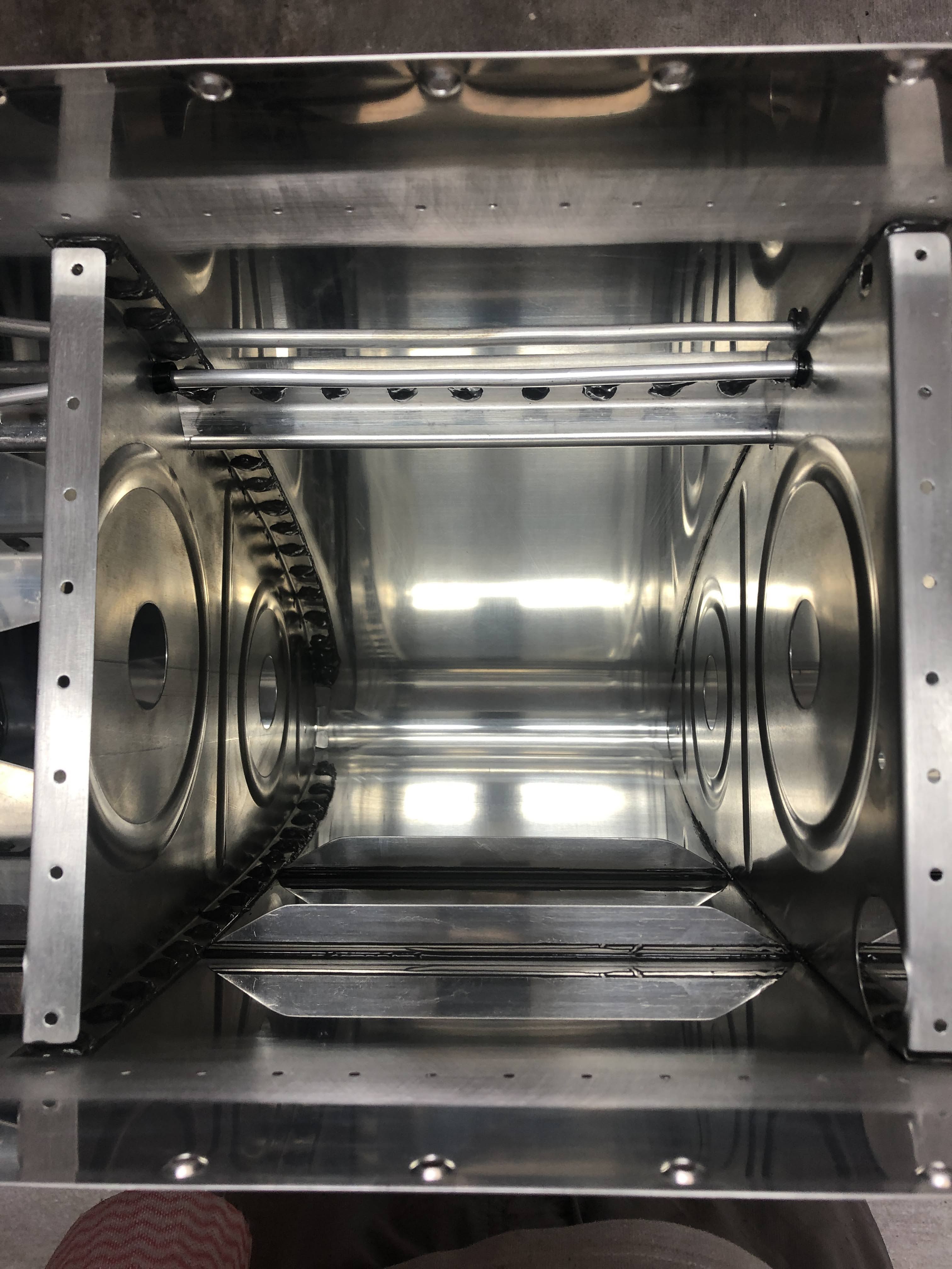
Here are some images taken through the filler cap and the fuel sender hole to show how the bead of sealant was pushed ahead by the baffle as it was installed. Hopefully this bead, combined with the sealant along the baffle flanges is enough to prevent any fuel leaking out of the baffle.
 |
| This image (through the filler cap) also shows the shop heads of the pulled rivets on the second rib flange. |
 |
| This is the bead through the fuel sender hole, between the bottom skin at the baffle. |
 |
| This is the bead from the skin to the end rib. |
For the record, here are the photos showing the RIGHT tank didn't have any cats or spiders living in it before i closed it up:
Once the sealant had cured, i countersunk all the remaining skin holes and squeezed rivets into those as well.
Since i had the countersink cage out, I countersunk the holes where the wing root gap filler nutplates are located. These are #19 holes (for a #8 screw) however the pilot for the #19 countersink cutter would not fit - so i used a #21 pilot countersink cutter instead and this fit into the nutplate threads.
Astute readers may notice that i did not cover the shop heads of the pulled rivets in sealant - this needs to be done however i only had a tiny bit of sealant left over - and i will use that for the fuel senders. I have some expired fuel sealant (flamemaster CS3204) - but i want to make a test coupon to make sure that this is still good to use to cover the shop heads.
Edit:
The test coupon showed that there was nothing wrong with the expired sealant, so it was used to cover all the shop heads on the back of the tank baffle (using the trick learned from Van's fuel tank video)
To end this little post - a satisfying video:


No comments:
Post a Comment